Mitsubishi Pajero Pinin. Manual - part 244


  Index      Mitsubishi     Mitsubishi Pajero Pinin - service repair manual 2001 year


Search            


Content   ..  242  243  244  245   ..


Mitsubishi Pajero Pinin. Manual - part 244


4

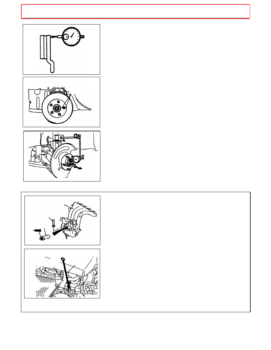
BRAKE DISC RUN-OUT CHECK AND CORRECTION

1.  Remove the brake assembly, and then hold it with wire.
2.  Place a dial gauge approximately 5 mm from the outer circumference

of the brake disc, and measure the run-out of the disc.

Limit: <Front> 0.06 mm or less,

<Rear> 0.08 mm or less

3.  If the brake disc run-out exceeds the limit, correct it as follows:

(1)  Chalk phase marks on the wheel stud and the brake disc, which

run-out is excessive as show

(2)  Remove the brake disc. Then place a dial gauge as shown, and

measure the end play by pushing and pulling the wheel hub.

Limit:  <Front> 0.2 mm, <Rear> 0.025 mm

(3)  If the end play exceeds the limit, disassemble the hub and knuckle

assembly to check each part.

(4) 

If the end play does not exceed the limit, dephase the brake disc

and secure it. Then recheck the brake disc run-out.

4.  If the run-out cannot be corrected by changing the phase of the brake

disc, replace the brake disc or grind it with the on-the-car type brake
lathe (”MAD, DL-8700PF” or equivalent.

BRAKE BOOSTER VACUUM NIPPLE
REPLACEMENT <SCREW TYPE NIPPLE>

1.  Remove the brake booster hose from the intake manifold.
2.  Replace the nipple with a new one, using a sealing agent and

tighten to 15 – 18 N.m.

Specified sealant:

3M ATD Part No.8661 or equivalent

Caution
Take care when applying the thread sealant as too much
could block the nipple.

3. 

After replacement, re-install the brake booster hose.

BRAKE BOOSTER VACUUM NIPPLE CLEANING
<PRESS FIT TYPE NIPPLE>

1.  Remove the brake booster hose from the intake manifold.
2.  Insert special tool into the nipple and remove the carbon deposit

by rotating and reciprocating of the special tool.

Caution
The special tool should be inserted more than 50 mm and
confirm that it goes through into the intake manifold.

3.  Make sure that no parts of the special tool remain in the manifold.

4.  After cleaning, re-install the brake booster hose.

3. Details: ’00 PAJERO PININ Workshop Manual chassis

BASIC BRAKE SYSTEM - On-vehicle Service

35A-13

<Added>

14F812

A14A0398

14H0052

AY0142BY

AY0143BY

Chalk marks

Intake minifold

Brake booster hose

Nipple

Brake booster hose

Nipple

MB991876

ANTI-SKID

BRAKING SYSTEM

(ABS) <4WD>

Click on the applicable bookmark to selected the required model year

35B-1

ANTI-SKID

BRAKING SYSTEM

(ABS) <4WD>

CONTENTS

GENERAL INFORMATION

3

. . . . . . . . . . . . . . . . . . 

SERVICE SPECIFICATIONS

3

. . . . . . . . . . . . . . . . . 

LUBRICANTS

Refer to GROUP 35A

. . . . . . . . . . 

SEALANTS

Refer to GROUP 35A

. . . . . . . . . . . . 

SPECIAL TOOLS

4

. . . . . . . . . . . . . . . . . . . . . . . . . . . 

TROUBLESHOOTING

5

. . . . . . . . . . . . . . . . . . . . . . . 

ON-VEHICLE SERVICE

22

. . . . . . . . . . . . . . . . . . . . 

Brake Pedal Check and Adjustment

Refer to GROUP 35A

. . . . . . . . . . . . . . . . . . . . . . . . . . 

Brake Booster Operating Test

Refer to GROUP 35A

. . . . . . . . . . . . . . . . . . . . . . . . . . 

Check Valve Operation Check

Refer to GROUP 35A

. . . . . . . . . . . . . . . . . . . . . . . . . . 

Load Sensing Spring Length Check and
Adjustment

Refer to GROUP 35A

. . . . . . . . . . . . . . . 

Load Sensing Proportioning Valve Function 
Test 

Refer to GROUP 35A

. . . . . . . . . . . . . . . . . . . . . 

Brake Fluid Level Sensor Check

Refer to GROUP 35A

. . . . . . . . . . . . . . . . . . . . . . . . . . 

Bleeding

Refer to GROUP 35A

. . . . . . . . . . . . . . . . . 

Disc Brake Pad Check and Replacement

Refer to GROUP 35A

. . . . . . . . . . . . . . . . . . . . . . . . . . 

Disc Brake Rotor Check

Refer to GROUP 35A

. . . 

Brake Disc Thickness Check

Refer to GROUP 35A

. . . . . . . . . . . . . . . . . . . . . . . . . . 

Brake Disc Run-out Check and Correction

Refer to GROUP 35A

. . . . . . . . . . . . . . . . . . . . . . . . . . 

Wheel Speed Sensor Output Voltage Check

22

. . . . . . . . . . . . . . . . . . . . . . . . . . . . . . . . . . . . . . . . . . . . 

ABS Warning Lamp Relay Continuity Check

23

. . . . . . . . . . . . . . . . . . . . . . . . . . . . . . . . . . . . . . . . . . . . 

Hydraulic Unit Check

24

. . . . . . . . . . . . . . . . . . . . . . . . 

Remedy for a Flat Battery

25

. . . . . . . . . . . . . . . . . . . 

BRAKE PEDAL

Refer to GROUP 35A

. . . . . . . . 

MASTER CYLINDER AND BRAKE 
BOOSTER 

Refer to GROUP 35A

. . . . . . . . . . . . 

CONTINUED ON NEXT PAGE

Click on the applicable bookmark to selected the required model year

35B-2

FRONT DISC BRAKE

Refer to GROUP 35A

. . 

REAR DISC BRAKE

Refer to GROUP 35A

. . . . 

LOAD SENSING PROPORTIONING 
VALVE

Refer to GROUP 35A

. . . . . . . . . . . . . . . . . 

HYDRAULIC UNIT AND ABS-ECU

26

. . . . . . . . . 

WHEEL SPEED SENSOR

29

. . . . . . . . . . . . . . . . . . 

G SENSOR

31

. . . . . . . . . . . . . . . . . . . . . . . . . . . . . . . 


Content   ..  242  243  244  245   ..