Mitsubishi Pajero Pinin. Manual - part 242
 

  Index      Mitsubishi     Mitsubishi Pajero Pinin - service repair manual 2001 year


Search            


Content   ..  240  241  242  243   ..


Mitsubishi Pajero Pinin. Manual - part 242


BASIC BRAKE SYSTEM – 

Master Cylinder and Brake Booster <1800-MPI>

35A-4

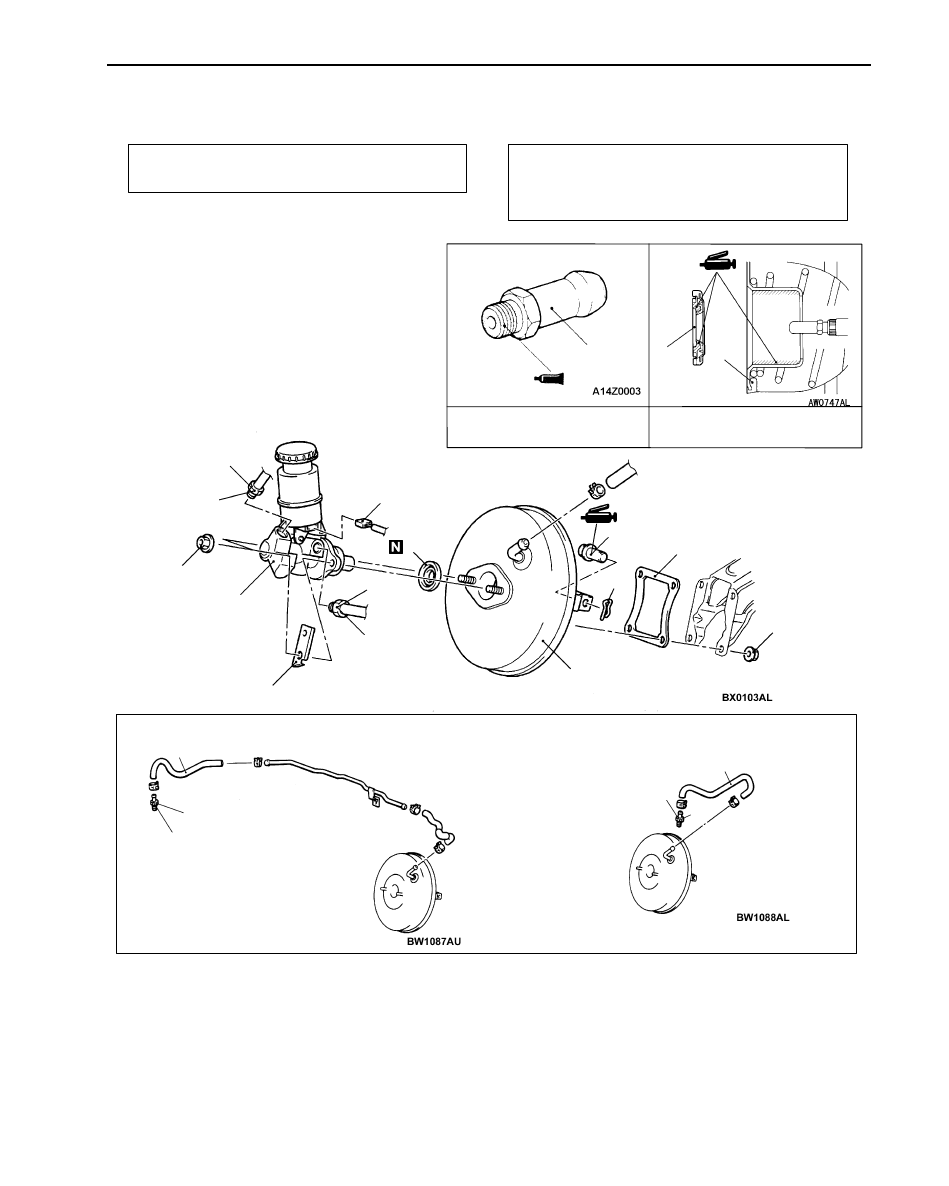
MASTER CYLINDER AND BRAKE BOOSTER <1800-MPI>

REMOVAL AND INSTALLATION

Pre-removal Operation
Brake Fluid Draining

Post-installation Operation

D

Brake Fluid Supplying and Air Bleeding (Refer to
P.35A-11.)*

D

Brake Pedal Adjustment (Refer to P.35A-7.)*

4

Specified Sealant: 3M ATD
Part No.8661 or equivalent

7

8

11

9

10

5

1

2

5

Grease: Silicone grease

1

3

9

<L.H. drive vehicles>

<R.H. drive vehicles>

6

11

6

11

14 

±

 2 N·m

15 

±

 1 N·m

15 

±

 1 N·m

16 

±

 1 N·m

16 

±

 1 N·m

9.8 

±

 2.0 N·m

BASIC BRAKE SYSTEM – 

Master Cylinder and Brake Booster <1800-MPI>

35A-5

Master cylinder removal steps

1. Brake pipe connection
2. Brake fluid level sensor connector
3. Bracket <L.H. drive vehicles>
4. Master cylinder

"

C

A

5. Seal

Brake booster removal steps

1. Brake pipe connection
2. Brake fluid level sensor connector
3. Bracket <L.H. drive vehicles>
4. Master cylinder

"

C

A

5. Seal

"

B

A D

Push rod protrusion amount check and
adjustment

"

A

A

6. Vacuum hose 

(With built-in check valve)

7. Snap pin
8. Pin assembly
9. Brake booster

10. Sealer

Fitting removal

11. Fitting

NOTE
(1) *: Refer to PAJERO PININ ’00 Workshop Manual 

(Pub. No. CKRE00E1).

(2) The installation service points are the same as before.

BASIC BRAKE SYSTEM – 

Rear Drum Brake

35A-6

REAR DRUM BRAKE

REMOVAL AND INSTALLATION

Pre-removal Operation

D

Loosening the Parking Brake Cable Adjusting Nut.
(Refer to GROUP 36 – On-vehicle Service)

D

Brake Fluid Draining

Post-installation Operation

D

Parking Brake Lever Stroke Adjustment
(Refer to GROUP 36 – On-vehicle Service)

D

Brake Fluid Supplying and Air Bleeding (Refer to
P.35A-11.)*

1

2

3

4

5

6

7

8

9

10

11

12

17

14

19

16

17

Specified grease: Brake grease SAE J310, NLGI No.1

7

6

8

18

15

13

4

3

14

17

4

15 

±

 1 N·m

9.8 

±

 1.9 N·m

Removal steps

1. Brake drum
2. Shoe-to-shoe spring
3. Adjuster lever
4. Auto-adjuster assembly
5. Retainer spring
6. Shoe hold-down cup
7. Shoe hold-down spring
8. Shoe hold-down cup
9. Shoe-to-shoe spring

10. Shoe and lining assembly

11. Shoe and lever assembly

A

A

" "

B

A

12. Retainer

"

A

A

13. Wave washer
14. Parking lever
15. Shoe and lining assembly
16. Shoe hold-down pin
17. Backing plate (Refer to GROUP 27

– Rear Axle Shaft.)

Wheel cylinder removal steps

1. Brake drum

18. Brake pipe connection
19. Wheel cylinder assembly

NOTE
*: Refer to PAJERO PININ ’00 Workshop Manual 
(Pub. No. CKRE00E1).

BASIC BRAKE SYSTEM – 

Rear Drum Brake

35A-7

REMOVAL SERVICE POINT

A

A

"

RETAINER REMOVAL

Use a flat-tipped screwdriver or the like to open up the retainer
joint, and remove the retainer.

INSTALLATION SERVICE POINTS

"

A

A

WAVE WASHER INSTALLATION

Install the wave washer in the direction shown in the illustration.

"

B

A

RETAINER INSTALLATION

Use pliers or the like to crimp the retainer or the pin positively.

INSPECTION

BRAKE LINING THICKNESS CHECK

Refer to P.35A-3.

BRAKE DRUM INSIDE DIAMETER CHECK

Refer to P.35A-3.

BRAKE LINING AND BRAKE DRUM CONTACT CHECK

Refer to P.35A-3.

Pin of shoe and lining assembly

Retainer

Wave washer

Shoe and lining
assembly

Pin

Parking lever

Pin of shoe and lining assembly

Retainer


Content   ..  240  241  242  243   ..