Mitsubishi Lancer Evolution 8. Manual - part 111
SRS AIRBAGS – TROUBLESHOOTING
52B-9
To next page
Replace the driver’s airbag module (squib)
Replace the clock spring
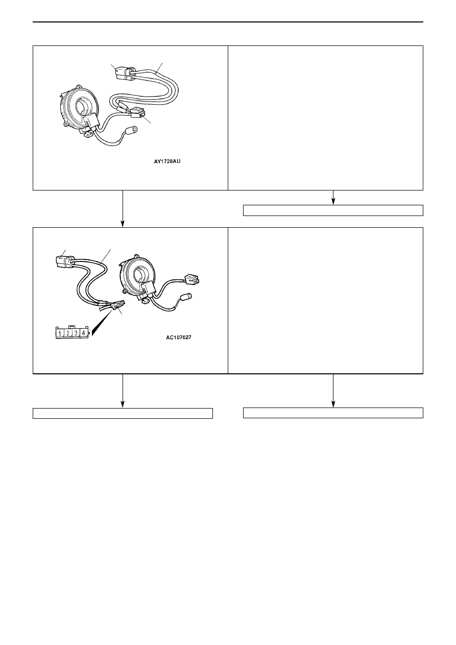
(Checking the driver’s airbag module (squib))
MUT-II/III diagnosis code
• Detach the (–) terminal of the battery
• Detach the driver’s airbag module connector C-207
• Connect the dummy resistor (MB991865) to the resistor
harness (MB 991866)
• Insert the probe of the resistor harness (MB991866) behind
the driver’s airbag module connector C-207 of the clock
spring
Caution
Do not insert the probe directly into the terminal from
the front side of the connector, as this may cause a
reduction in contact pressure.
• Connect the (–) terminal of the battery.
• After erasing the diagnosis code memory, reconfirm the
diagnosis code.
Is Code No.21 output?
(Checking the clock spring)
MUT-II/III diagnosis code
• Detach the (–) terminal of the battery
• Detach the clock spring connector (4 pin) C-204
• Connect the dummy resistor (MB991865) to the resistor
harness (MB991866)
• Insert the probe of the resistor harness (MB991866)
between terminal 3 and 4, behind the clock spring connector
C-204 (harness side)
Caution
Do not insert the probe directly into the terminal from
the front side of the connector, as this may cause a
reduction in contact pressure.
• Connect the (–) terminal of the battery.
• After erasing the diagnosis code memory, reconfirm the
diagnosis code.
Is Code No.21 output?
(Type 1)
Dummy resistor
(MB991865)
resistance (3
Ω
)
Resistor harness
MB991866
C-207
Driver’s airbag module
connector
Dummy resistor
MB991865
resistance (3
Ω
)
Resistor harness
MB991866
C-204 Clock spring connector
(harness side)
NO
YES
YES
NO