Mitsubishi Lancer Evolution 7. Manual - part 243


  Index      Mitsubishi     Mitsubishi Lancer Evolution 7 - service repair manual


Search            


Content   ..  241  242  243  244   ..


Mitsubishi Lancer Evolution 7. Manual - part 243


CLUTCH OVERHAUL -

Clutch

21B-3

CLUTCH

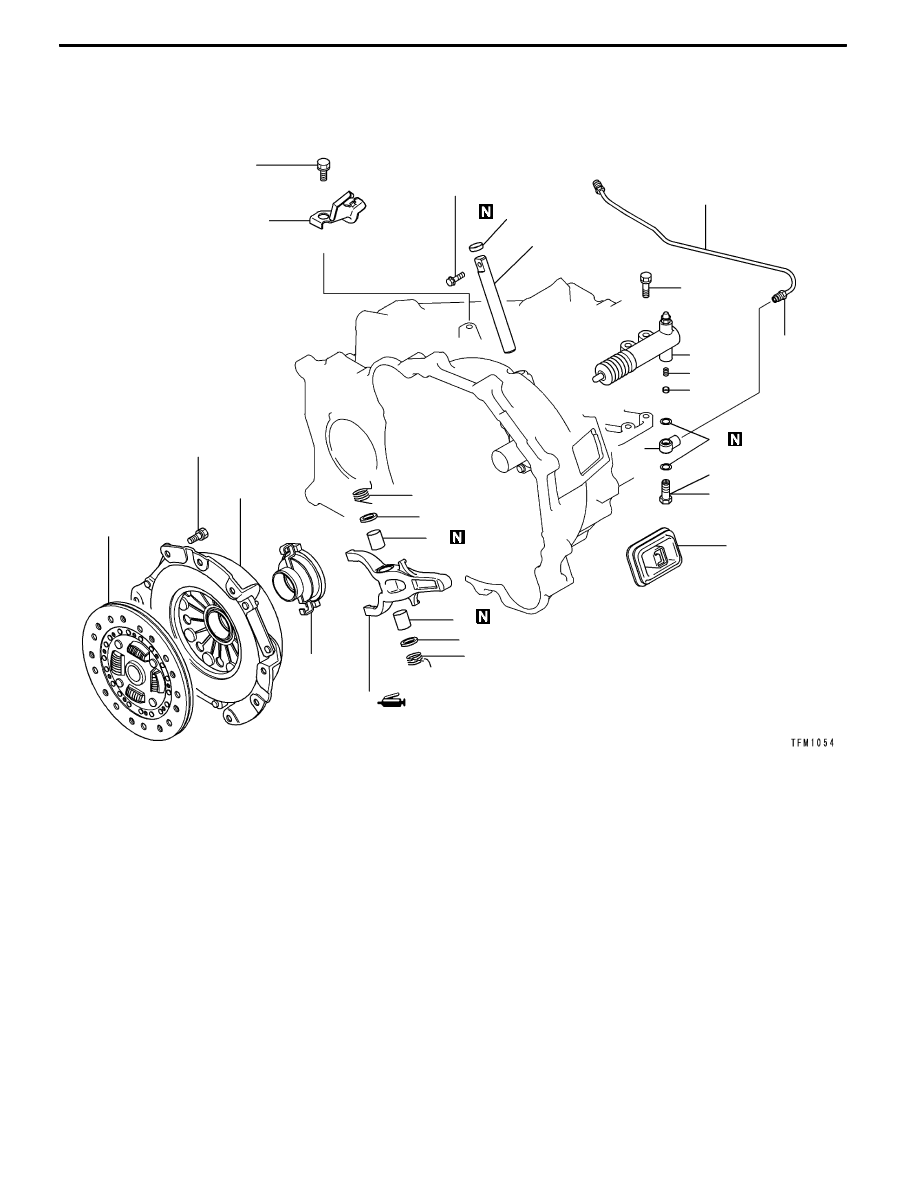
REMOVAL AND INSTALLATION

18 ± 3 Nm

1

11

12

9

10

17

15

19

18

16

18 ± 3 Nm

9.8 ± 2 Nm

18 ± 3 Nm

15 ± 2 Nm

22 ± 2 Nm

16

14

13

20

2

8

7

6

3

4

5

Removal steps

1. Clutch fluid line bracket

2. Clutch tube

3. Union bolt

4. Union

5. Gasket

"

EA 6. Valve plate

"

EA 7. Valve plate spring

"

DA 8. Clutch release cylinder

9. Clutch cover

10. Clutch disc

"

CA 11. Sealing cap

12. Release fork shaft

13. Support spring (L)

14. Packing

"

BA 15. Release fork

"

AA 16. Bush

17. Clutch release bearing

18. Packing

19. Support spring (R)

20. Release fork boot

CLUTCH OVERHAUL -

Clutch

21B-4

REASSEMBLY SERVICE POINTS

"

ABUSH INSTALLATION

Press the bush into the position of the release valve shown

in the illustration.

"

BRELEASE FORK INSTALLATION

Apply grease on the release fork at the position shown in

the illustration.

Grease

Specified grease:

MITSUBISHI genuine grease Part No.0101011

or equivalent

"

CSEALING CAP INSTALLATION

Press the sealing cap into the position shown in the illustration

while taking care so that it is not tilted.

"

DCLUTCH RELEASE CYLINDER INSTALLATION

Fill grease in the release fork to the position shown in the

illustration.

Grease

Specified grease:

MITSUBISHI genuine grease Part No.0101011

or equivalent

"

EVALVE PLATE SPRING/VALVE PLATE

INSTALLATION

Set the spring’s large diameter side to the valve plate side,

and install the valve plate spring and valve plate.

Bush

2 mm

Release fork

Valve plate spring

Release cylinder

Valve plate

CLUTCH OVERHAUL -

Clutch

21B-5

INSPECTION

CLUTCH COVER
(1) Check the pressure plate surface for wear, cracks or

discoloration.

(2) Check the strap plate rivet for looseness. If loose, replace

the clutch cover.

CLUTCH DISC
Caution

Do not wash the clutch disc with cleaning oil.
(1) Check the facing for decomposition caused by rivet

looseness, single-side contact or seizure, and check for

the presence of grease. If any fault is found, replace

the clutch disc.

(2) Measure the rivet sinking level, and replace the clutch

disc if the limit is exceeded.
Limit value: 0.3 mm

(3) Check the torsion spring for play and breakage. If faulty,

replace the clutch disc.

(4) Set the clutch disc onto the input shaft, and check the

sliding state and for play in the rotation direction. If the

sliding state is poor, wash the disc, reassemble and then

check the state again. If there is extreme play, replace

the clutch disc or input shaft or both parts.

CLUTCH RELEASE BEARING
Caution

Grease is filled in the release bearing, so do not wash with

washing oil.
(1) Check the bearing for seizure, damage, abnormal noise

or improper rotation.

(2) Check that the pull ring of the release bearing is not

worn.

(3) If the surface where the bearing contacts the release

fork is abnormally worn, replace the bearing.

RELEASE FORK AND RELEASE FORK SHAFT
(1) If the surface where the release fork contacts the bearing

is abnormally worn, replace the release fork.

(2) Check the release fork shaft for bending and wear. If

any abnormality is found, replace the release fork shaft.

CLUTCH OVERHAUL -

Clutch Release Cylinder

21B-6

CLUTCH RELEASE CYLINDER

DISASSEMBLY AND REASSEMBLY

5

3

4

1

2

6

7

8

11 ± 1 Nm

Disassembly step

1. Cap

2. Air breather

3. Push rod

4. Boot

"

AA 5. Piston cup

"

AA 6. Piston

7. Conical spring

8. Release cylinder


Content   ..  241  242  243  244   ..