Mitsubishi Grandis. Manual - part 522


  Index      Mitsubishi     Mitsubishi Grandis - service repair manual


Search            


Content   ..  520  521  522  523   ..


Mitsubishi Grandis. Manual - part 522


DIAGNOSIS

CONTROLLER AREA NETWORK (CAN)

54D-186

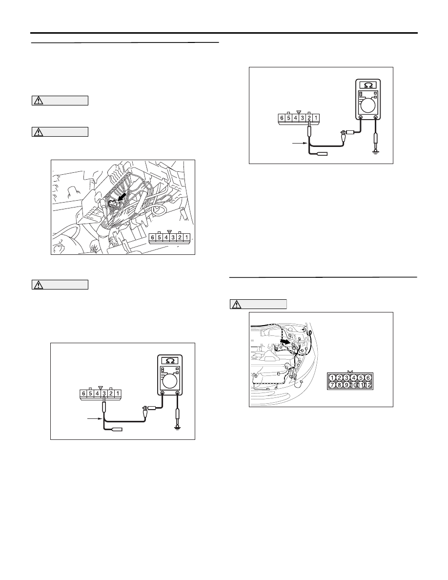
STEP 21. Resistance measurement at the A-07 
joint connector (CAN1).
NOTE: When checking A-07 joint connector (CAN1), 
disassemble and check the engine compartment 
relay box by referring to 

P.54D-616

.

CAUTION

A digital multimeter should be used. For details 
refer to 

P.54D-8

.

CAUTION

The test wiring harness should be used. For 
details refer to 

P.54D-8

.

(1) Disconnect the connector, and measure at the 

wiring harness side.

CAUTION

When measuring the resistance, disconnect the 
negative battery terminal. For details refer to 

P.54D-8

.

(2) Ensure that the negative battery terminal is 

disconnected.

(3) Resistance between A-07 joint connector (CAN1) 

terminal No.3 and body earth

OK: 1 k

 or more

(4) Resistance between A-07 joint connector (CAN1) 

terminal No.2 and body earth

OK: 1 k

 or more

Q: Are the check result normal?

YES <all of the measurement results show 1 k

 or 

more> : 

Go to Step 27 .

NO <The resistance between terminal No.3 and 
body earth is less than 1 k

> : 

Go to Step 22 .

NO <The resistance between terminal No.2 and 
body earth is less than 1 k

> : 

Go to Step 25 .

STEP 22. Connector check: A-16 intermediate 
connector

CAUTION

The strand end of the twist wire should be within 
10 cm from the connector. For details refer to 

P.54D-8

.

Q: Is the check result normal?

YES : 

Go to Step 23 .

NO : 

Repair the defective connector.

AC302572AD

Connector: A-07

Harness side

AC209364

Harness side: A-07

AC209364LN

Test
harness

AC209364

Harness side: A-07

AC209364LO

Test
harness

AC310403

AC

Connector: A-16 <LHD>

A-16 (B)

DIAGNOSIS

CONTROLLER AREA NETWORK (CAN)

54D-187

STEP 23. Resistance measurement at the A-07 
joint connector (CAN1).
NOTE: When checking A-07 joint connector (CAN1), 
disassemble and check the engine compartment 
relay box by referring to 

P.54D-616

.

CAUTION

A digital multimeter should be used. For details 
refer to 

P.54D-8

.

CAUTION

The test wiring harness should be used. For 
details refer to 

P.54D-8

.

(1) Disconnect the joint connector (CAN1) and the 

intermediate connector, and measure at the 
wiring harness side.

CAUTION

When measuring the resistance, disconnect the 
negative battery terminal. For details refer to 

P.54D-8

.

(2) Ensure that the negative battery terminal is 

disconnected.

(3) Resistance between A-07 joint connector (CAN1) 

terminal No.3 and body earth

OK: 1 k

 or more

Q: Is the check result normal?

YES : 

<1 k

Ω or more> Go to Step 24.

NO : 

<less than 1 k

Ω> Repair the wiring harness 

between the joint connector (CAN1) and the 
intermediate connector.

STEP 24. Resistance measurement at the A-16 
intermediate connector.

CAUTION

A digital multimeter should be used. For details 
refer to 

P.54D-8

.

CAUTION

The test wiring harness should be used. For 
details refer to 

P.54D-8

.

(1) Disconnect the engine-ECU <M/T> or 

engine-A/T-ECU <A/T> connector and the 

AC302572AD

Connector: A-07

Harness side

AC310403

AC

Connector: A-16 <LHD>

A-16 (B)

AC209364

Harness side: A-07

AC209364LN

Test
harness

AC310403

AC

Connector: A-16 <LHD>

A-16 (B)

AC310615

AS

Harness side

Connector: C-112 <LHD>

C-112 (GR)

61

62

63

64

65

66

67

68

69

70

71

72

73

74

75

76

77

78

79

80

81

82

83

84

85

86

87

88

89

DIAGNOSIS

CONTROLLER AREA NETWORK (CAN)

54D-188

intermediate connector, and measure at the 
wiring harness side.

CAUTION

When measuring the resistance, disconnect the 
negative battery terminal. For details refer to 

P.54D-8

.

(2) Ensure that the negative battery terminal is 

disconnected.

(3) Resistance between A-16 intermediate connector 

terminal No.12 and body earth

OK: 1 k

 or more

CAUTION

Strictly observe the specified wiring harness 
repair procedure. For details refer to 

P.54D-8

.

Q: Is the check result normal?

YES : 

<1 k

Ω or more> Follow diagnostic item 17, 

Diagnose CAN bus lines thoroughly. Refer 
to 

P.54D-452

.

NO : 

<less than 1 

Ω> Repair the wiring harness 

between the intermediate connector and the 
engine-ECU <M/T> or engine-A/T-ECU 
<A/T> connector.

STEP 25. Connector check: A-03 ABS-ECU 
connector

CAUTION

The strand end of the twist wire should be within 
10 cm from the connector. For details refer to 

P.54D-8

.

Q: Is the check result normal?

YES : 

Go to Step 26 .

NO : 

Repair the defective connector.

STEP 26. Resistance measurement at the A-07 
joint connector (CAN1).
NOTE: When checking A-07 joint connector (CAN1), 
disassemble and check the engine compartment 
relay box by referring to 

P.54D-616

.

CAUTION

A digital multimeter should be used. For details 
refer to 

P.54D-8

.

CAUTION

The test wiring harness should be used. For 
details refer to 

P.54D-8

.

(1) Disconnect the joint connector (CAN1) and the 

ABS-ECU connector, and measure at the wiring 
harness side.

CAUTION

When measuring the resistance, disconnect the 
negative battery terminal. For details refer to 

P.54D-8

.

(2) Ensure that the negative battery terminal is 

AC209364

AC209364

AC209364

Male side: A-16

AC209364EF

Test
harness

AC310401

Connector: A-03 <LHD>

Harness side

AK

AC310401

Connector: A-03 <LHD>

Harness side

AK

AC302572AD

Connector: A-07

Harness side

DIAGNOSIS

CONTROLLER AREA NETWORK (CAN)

54D-189

disconnected.

(3) Resistance between A-07 joint connector (CAN1) 

terminal No.2 and body earth

OK: 1 k

 or more

CAUTION

Strictly observe the specified wiring harness 
repair procedure. For details refer to 

P.54D-8

.

Q: Is the check result normal?

YES : 

<1 k

Ω or more> Follow diagnostic item 17, 

Diagnose CAN bus lines thoroughly. Refer 
to 

P.54D-452

.

NO : 

<less than 1 k

Ω> Repair the wiring harness 

between the joint connector (CAN1) and the 
ABS-ECU connector.

STEP 27. Resistance measurement at the A-07 
joint connector (CAN1).
NOTE: When checking A-07 joint connector (CAN1), 
disassemble and check the engine compartment 
relay box by referring to 

P.54D-616

.

CAUTION

A digital multimeter should be used. For details 
refer to 

P.54D-8

.

CAUTION

The test wiring harness should be used. For 
details refer to 

P.54D-8

.

(1) Disconnect the joint connector (CAN1) and the 

intermediate connector, and measure at the 
wiring harness side.

CAUTION

When measuring the resistance, disconnect the 
negative battery terminal. For details refer to 

P.54D-8

.

(2) Ensure that the negative battery terminal is 

AC209364

Harness side: A-07

AC209364LO

Test
harness

AC302572AD

Connector: A-07

Harness side

AC310613

AD

Connector: C-125 <LHD>


Content   ..  520  521  522  523   ..