Mitsubishi Grandis. Manual - part 322


  Index      Mitsubishi     Mitsubishi Grandis - service repair manual


Search            


Content   ..  320  321  322  323   ..


Mitsubishi Grandis. Manual - part 322


TROUBLESHOOTING

HEATER, AIR CONDITIONER AND VENTILATION

55-173

YES : 

The trouble can be an intermittent 

malfunction (Refer to GROUP 00, How to 
Cope with Intermittent Malfunction 

P.00-5

.)

NO : 

Repair the wiring harness.

Step 5. Connector check: C-106 A/C-ECU 
connector

Q:  Is the check result normal?

YES : 

Go to Step 6.

NO : 

Repair the connector.

Step 6. Check the wiring harness between C-30 
PTC heater switch connector terminal No.1 and 
C-106 A/C-ECU connector terminal No.26.

• Check the PTC heater switch earth line for open 

circuit.

Q: Is the check result normal?

YES : 

The trouble can be an intermittent 

malfunction (Refer to GROUP 00, How to 
Cope with Intermittent Malfunction 

P.00-5

.)

NO : 

Repair the wiring harness.

AC310631AC

Connector: C-105 <RHD>

Harness side

31

32

33

34

35

36

37

38

39

40

41

42

43

44

45

46

AC310632AZ

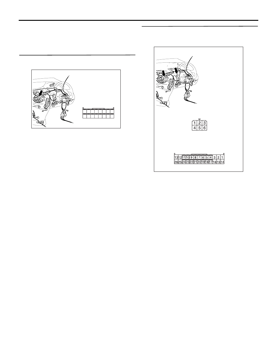
Connectors: C-30, C-106 <RHD>

C-30

C-106

C-30

C-106

Harness side

Harness side

TROUBLESHOOTING

HEATER, AIR CONDITIONER AND VENTILATION

55-174

INSPECTION PROCEDURE 26: A/C-ECU power supply system <LHD>

CIRCUIT OPERATION

If a power supply is not provided to the A/C-ECU, the 
A/C-ECU power supply system or the earth system 
may be defective.

POSSIBLE CAUSES

• Malfunction of the A/C-ECU

• Damaged harness wires and connectors

IGNITION
SWITCH (IG2)

IGNITION
SWITCH (ACC)

A/C-ECU

Wire colour code
B : Black     LG : Light green     G : Green     L : Blue     W : White     Y : Yellow     SB : Sky blue
BR : Brown     O : Orange     GR : Gray     R : Red     P : Pink     V : Violet

RELAY
BOX

POWER
SOURCE

POWER
SOURCE

BATTERY
BACK-UP

RELAY
BOX

FUSIBLE
LINK

26

A/C-ECU Power Supply Circuit

TROUBLESHOOTING

HEATER, AIR CONDITIONER AND VENTILATION

55-175

DIAGNOSIS

Step 1. Connector check: C-106 A/C-ECU 
connector

Q:  Is the check result normal?

YES : 

Go to Step 2.

NO : 

Repair the connector.

Step 2. Voltage measurement at C-106 A/C-ECU 
connector.

(1) Disconnect the connector, and measure at the 

wiring harness side.

(2) Turn the ignition switch to the ON position.

(3) Measure the voltage between terminal 6 and 

body earth.

OK: System voltage

Q: Is the check result normal?

YES : 

Go to Step 4.

NO : 

Go to Step 3.

Step 3. Check the wiring harness between C-106 
A/C-ECU connector terminal No.6 and the 
ignition switch (IG2).

NOTE: 

Prior to the wiring harness inspection, check joint 
connector C-31 and junction block connector C-205 
and C-202, and repair if necessary.

• Check the A/C-ECU power supply line for open 

circuit.

Q: Is the check result normal?

AC310613

AB

Connector: C-106 <LHD>

Harness side

AC310613

AB

Connector: C-106 <LHD>

Harness side

AC310507

Connector C-106 
(Harness side)

BI

AC310614

BH

Connectors: C-31, C-106 <LHD>

C-31

C-106

C-31

C-106

Harness side

AC310624

Connectors: C-202, C-205 <LHD>

AF

Junction block (Front view)

C-205

C-202

C-205

Harness side

C-202

Harness side

TROUBLESHOOTING

HEATER, AIR CONDITIONER AND VENTILATION

55-176

YES : 

The trouble can be an intermittent 

malfunction (Refer to GROUP 00, How to 
Cope with Intermittent Malfunction 

P.00-5

.)

NO : 

Repair the wiring harness.

Step 4. Voltage measurement at C-106 A/C-ECU 
connector.

(1) Disconnect the connector, and measure at the 

wiring harness side.

(2) Turn the ignition switch to the ON position.

(3) Measure the voltage between terminal 5 and 

body earth.

OK: System voltage

Q: Is the check result normal?

YES : 

Go to Step 6.

NO : 

Go to Step 5.

Step 5. Check the wiring harness between C-106 
A/C-ECU connector terminal No.5 and the 
ignition switch (ACC).

NOTE: Prior to the wiring harness inspection, check 
joint connector C-32 and intermediate connector 
C-125, and repair if necessary.

• Check the A/C-ECU power supply line for open 

circuit.

Q: Is the check result normal?

YES : 

The trouble can be an intermittent 

malfunction (Refer to GROUP 00, How to 
Cope with Intermittent Malfunction 

P.00-5

.)

NO : 

Repair the wiring harness.

Step 6. Voltage measurement at C-106 A/C-ECU 
connector.

(1) Disconnect the connector, and measure at the 

AC310613

AB

Connector: C-106 <LHD>

Harness side

AC310507

Connector C-106 
(Harness side)

BJ

AC310614

AQ

Connectors: C-32, C-106, C-125 <LHD>

C-106

C-125

C-106

Harness side

C-125

C-32

C-32

AC310613

AB

Connector: C-106 <LHD>

Harness side


Content   ..  320  321  322  323   ..