Mitsubishi L200. Manual - part 12


  Index      Mitsubishi     Mitsubishi L200 - service repair manual 2012 year


Search            


Content   ..  10  11  12  13   ..


Mitsubishi L200. Manual - part 12


PRECAUTIONS BEFORE SERVICE

GENERAL

00-44

For this reason, when the injector or engine-ECU is 
replaced, injector correction data must be registered 
afterwards in the engine-ECU using the Multi Use 
Tester III (M.U.T.-III).
Correction data is converted into an identification 
code consisting of 30 alphanumeric characters and 
printed on the injector connector.

REGISTRATION PROCEDURE

1. When replacing the engine-ECU, connect the 

current engine-ECU to the body harness.

NOTE: This operation is purposed to read the injec-
tor identification code stored in the engine-ECU. 
Reading the identification code in this way before 
replacement can eliminate manual input of the identi-
fication code after replacement.
2. After the ignition switch is in "LOCK" (OFF) 

position, connect the M.U.T.-III to the diagnosis 
connector.

3. Turn the ignition switch to "ON" position.
4. Select SPECIAL FUNCTION from the function 

menu.

5. When the current engine-ECU is still mounted, 

read and register the injector identification code 
as follows:
(1) Select Read Injector ID Code (for engine-ECU 

replacement) from the SPECIAL FUNCTION 
menu.

(2) Select Write and Save Injector ID Code from 

the menu to read data from the current engine-
ECU and save the data if it could be read 
normally.

(3) Mount the new engine-ECU on the vehicle.
(4) Select SPECIAL FUNCTION from the function 

menu.

(5) Select Write Injector ID Code (for engine-ECU 

replacement) from the SPECIAL FUNCTION 
menu.

(6) Select SAVED INJECTOR ID WRITING from 

the Write Injector ID Code menu to write the 
data, which was saved previously, to the 
engine-ECU.

6. If the injector has been replaced or data has not 

been read from the current engine-ECU, register 
the injector identification code as follows:
(1) Select Write Injector ID Code from the 

SPECIAL FUNCTION menu.

(2) If the injector was replaced, specify whether to 

write to every cylinder or a specific cylinder.
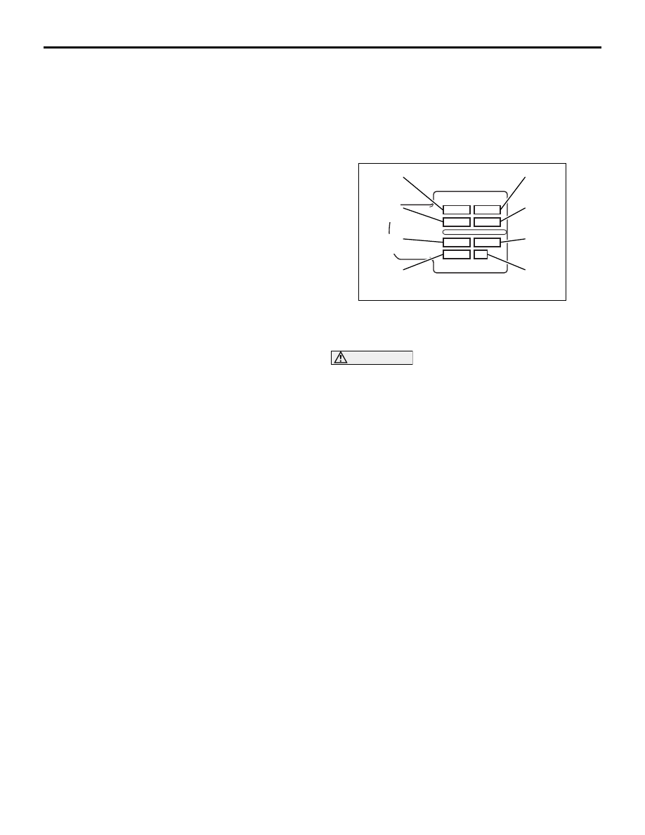
AK501492

Frame 1
(4 digits)

Frame 3
(4 digits)

Frame 5
(4 digits)

Frame 7
(4 digits)

Frame 2
(4 digits)

Frame 4
(4 digits)

Frame 6
(4 digits)

Frame 8
(2 digits)

AB

(3) Select the write mode from the menu, enter 

the identification code printed on the injector, 
and execute writing.

CAUTION

Even if the number of the cylinder to be regis-
tered does not match the actual injector mount-
ing location, registration ends normally. Specify 
the cylinder number correctly.
NOTE: The identification code is displayed in order 
of the frame numbers when it is read.
7. Makes sure that the engine warning lamp that is 

on changes to blinking, indicating the registration 
is complete.

NOTE: When the injector is replaced, executing the 
write operation also clears the values of small injec-
tion quantity learning.
8. Execute small injection quantity learning.

Refer to 

P.00-45

, the SMALL INJECTION 

QUANTITY LEARNING PROCEDURE for the 
learning procedure.

9. Confirm that the engine warning lamp is off.

Confirm also that the diagnosis code is not stored.

PRECAUTIONS BEFORE SERVICE

GENERAL

00-45

SMALL INJECTION QUANTITY LEARNING PROCEDURE

M1001014300322

CAUTION

1. If small injection quantity learning has not 

been executed, the engine warning lamp 
blinks.

2. When the requirements for learning are satis-

fied by operation after replacement of the 
engine-ECU, learning is automatically exe-
cuted even if no instruction is given from the 
M.U.T.-III. Accordingly, the malfunction indica-
tor lamp goes off. However, the learning thus 
executed is tentative and limited. Be sure to 
complete leaning using the M.U.T.-III.

PURPOSE

To keep emission and noise level at adequate levels, 
the engine-ECU must learn injector fuel injection in 
idle mode.
During learning, the engine-ECU calculates actual 
injection from each cylinder based on changes in 
engine speeds and corrects pilot injection control. It 
then keeps records of this amount of correction as a 
learned value.
For this reason, after the engine-ECU or injector is 
replaced, learning must be executed using the 
M.U.T.-III.
NOTE: Engine friction changes or injector deteriora-
tion over time may cause fluctuation in pilot injection. 
After use over time, it may prevent injection of an 
accurate amount of fuel according to the indication 
by the engine-ECU. This is why learning must be 
executed again periodically.
For this reason, the engine-ECU periodically leans 
injection according to the cumulative mileage.
Note that making the M.U.T.-III learn again resets the 
cumulative mileage.

NOTE: The engine sound may change or idling 
engine speeds may increase during injection learn-
ing. These are not abnormalities.

LEARNING PROCEDURE

1. After the ignition switch is in "LOCK" (OFF) 

position, connect the M.U.T.-III to the diagnosis 
connector.

2. Put the vehicle in the following idling stable 

conditions:

• Engine coolant temperature: 80 − 90°C

• Fuel temperature: 30 − 100°C

• Intake air temperature: −30 to 100°C

• Barometric pressure: 70 kPa or more

• Automatic transmission fluid temperature: 60°C 

or higher

• Lamps, A/C condenser fan and all accessories: 

OFF

• Transmission: Neutral <M/T>, "P" range <A/T>

• Power steering: Static state

3. Select SPECIAL FUNCTION from the function 

menu.

4. Select LEARNING from the SPECIAL FUNCTION 

menu.

5. Select Item No. 1 Small injection quantity learning 

to execute learning.

CAUTION

If the vehicle conditions go out of the learning 

conditions during idling, learning is interrupted.

 To reexecute learning, the ignition switch 

must once be turned off.
6. Continue idling for about 3 minutes before 

learning is completed.

7. Confirm that the engine warning lamp is off. If it 

still blinks, reexecute learning.

SUPPLY PUMP CORRECTION LEARNING PROCEDURE

M1001014400299

PURPOSE

The engine-ECU learns the relation between the 
suction control valve (linear solenoid valve) of the 
supply pump drive current and the fuel injection vol-
ume.
The learning value is calculated from the suction 
control valve drive current and the rail pressure sen-
sor output voltage.
When the supply pump is replaced, therefore, this 
learning must be executed.

Re-learning is executed when the engine is idling 
after the learning value in the engine-ECU has been 
reset by the M.U.T.-III.

LEARNING PROCEDURE

After the ignition switch is in "LOCK" (OFF) position, 

connect the M.U.T.-III to the diagnosis connector.

1. Turn the ignition switch to "ON" position. (Do not 

start the engine.)

2. Select SPECIAL FUNCTION from the function 

menu.

PRECAUTIONS BEFORE SERVICE

GENERAL

00-46

3. Select INITIALIZATION from SPECIAL 

FUNCTION menu.

4. Select and initialize Item No. 21 Supply pump 

exchange service.

5. After initializing, run the engine at idle in the 

following conditions.

• Accelerator pedal: OFF

• Engine coolant temperature: 60°C or higher

• Fuel temperature: 30°C or higher

6. Confirm that the item No. 65 High pressure pump 

learned status on M.U.T.-III Service Data is "2".

NOTE: "2" indicates that the learning has completed.

INITIALIZATION PROCEDURE FOR 
LEARNING VALUE IN DIESEL 
PARTICULATE FILTER (DPF) SYSTEM 
<Euro5>

M1001015600069

PURPOSE
The engine-ECU stores the change of the DPF sys-
tem caused by the various driving conditions as the 
learning value and uses it for assumption of the PM 
accumulated amount or for the acceptance/rejection 
criteria of the DPF system. For this reason, the learn-
ing value is necessary to be initialized when the parts 
related to the DPF system are replaced.

INITIALISATION PROCEDURE
1. After the ignition switch is in "LOCK" (OFF) 

position, connect M.U.T.-III with the diagnosis 
connector.

2. Ignition switch is in "ON" position.
3. Select the "SPECIAL FUNCTION" from the 

"FUNCTION MENU" on the M.U.T.-III.

4. Select the INITIALIZATION from the SPECIAL 

FUNCTION.

5. Select the item on the screen of the initialization 

for learning, and perform the initialization.

Service

Item 
No.

Item

At replacing DPF

40

DPF exchange service

At replacing 
exhaust differential 
pressure sensor

41

DPF differential 
pressure sensor 
exchange service

At replacing 
catalytic converter

42

DPF system 
malfunction service

BATTERY CURRENT SENSOR 
CALIBRATION <Euro5>

M1001018600240

PURPOSE

The engine-ECU carries out the electrical generation 
control according to the charge level of the battery, 
based on the battery current sensor signal. To 
improve the effect of reducing the fuel consumption 
by the electrical generation control, it is necessary to 
accurately detect the charge level of the battery. For 
this, if the following services are performed, carry out 
the battery current sensor calibration.

• Replacing the battery current sensor

• Replacing the engine-ECU

LEARNING PROCEDURE

1. After the ignition switch is in "LOCK" (OFF) 

position, disconnect the battery cable from the 
negative battery terminal.

AKB00261AB

Battery current
sensor

2. Remove the battery current sensor from the 

battery cable (Do not disconnect the battery 
current sensor connector).

3. Connect the battery cable without the battery 

current sensor to the negative battery terminal.

AC509179

AB

Diagnosis

connector

MB991827

MB991824 

MB991910

<LH drive vehicles>

AC501413AC

Diagnosis

connector

MB991827

MB991824 

MB991910

<RH drive vehicles>

PRECAUTIONS BEFORE SERVICE

GENERAL

00-47

4. Connect the M.U.T.-III to the diagnosis connector 

(But do not start the engine).

5. Turn the ignition switch to the ON position.
6. Select "MPI/GDI/DIESEL" from System select 

Screen of the M.U.T.-III.

7. Select "Special Function" from MPI/GDI/DIESEL 

Screen.

8. Select "Learning" from Special Function Screen.

9. Select "Battery current SNSR.calibration" from 

Learning Screen.

10.Start the calibration by pressing the "OK" button.
11.Confirm that the M.U.T.-III data list item No. 452 

Battery current sensor calibration is "Completed".

12.After the ignition switch is in "LOCK" (OFF) 

position, disconnect the M.U.T.-III.

13.Install the battery current sensor.

HOW TO USE THE THROTTLE 
CONTROLLER

M1001009300036

As for a vehicle with the electronic control throttle 
valve

*

, engine operations such as racing can not be 

performed from outside the vehicle. Thus, the throttle 
valve controller (MB991791) is provided as a special 
tool to enable the engine operation from outside the 
vehicle.
NOTE: 

*

: A vehicle with the accelerator pedal posi-

tion sensor (APS) installed to the accelerator pedal
THE THROTTLE CONTROLLER CONNECTION

AC103781

MB991791

MB991894

APS harness 
side connector

AC

1. Disconnect the accelerator pedal position sensor 

(APS) connector installed to the accelerator 
pedal, and connect the 6-pin connector of throttle 
controller adaptor (MB991894) to the vehicle 
harness-side connector. 

2. Connect the throttle controller (MB991791) to the 

8-pin connector of throttle controller adaptor 
(MB991894).

APPLICATION OF ANTI-CORROSION 
AGENTS AND UNDERCOATS

M1001011000247

If oil or grease gets onto the oxygen sensor, it will 
cause a drop in the performance of the sensor. 
Cover the oxygen sensor with a protective cover 
when applying anti-corrosion agents and undercoats.


Content   ..  10  11  12  13   ..