Mazda 6. Manual - part 332
T–88
THEFT-DETERRENT SYSTEM
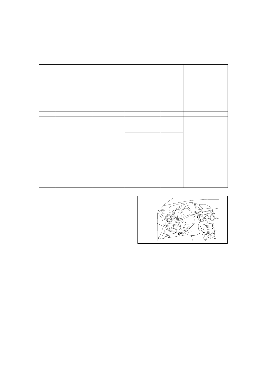
W Terminal Inspection
1. Connect SST (WDS or equivalent) to the vehicle
DLC-2 16-pin connector.
2. Access and monitor RPM of PID using SST
(WDS or equivalent).
• If engine speed signal normal, go to next step.
• If engine speed signal abnormal, inspect the
ABS (ABS/TCS) HU/CM, DSC HU/CM and
related wiring harness.
3. Inspect for continuity between the ABS (ABS/
TCS) HU/CM terminal X and the theft-deterrent
control module terminal W, or DSC HU/CM
terminal AB and the theft-deterrent control
module terminal W using an ohmmeter.
• If not continuity, replace the related wiring
harness.
• If wiring harness is normal, replace the theft-deterrent control.
End Of Sie
T
Lock/unlock
• Passenger’s
door lock-link
switch
• Rear door
lock-link switch
Passenger’s and rear
door lock-link switch
locked: inspect for
continuity to ground
No
• Inspect passenger’s or
rear door lock-link switch
(See
(See
• Inspect related harness
Passenger’s or any
rear door lock-link
switch unlocked:
inspect for continuity
to ground
Yes
U
—
—
—
—
—
V
Lock/unlock
• Driver’s door
lock-link switch
Driver’s door lock-link
switch locked: inspect
for continuity to
ground
No
• Inspect driver’s door
lock-link switch
(See
• Inspect related harness
Driver’s door lock-link
switch unlocked:
inspect for continuity
to ground
Yes
W
Engine speed
• ABS (ABS/TCS)
HU/CM (with
ABS (ABS/
TCS))
• DSC HU/CM
(with DSC)
—
• Inspect ABS (ABS/TCS)
HU/CM
(See
• Inspect DSC HU/CM
(See
• Inspect related harness
X
—
—
—
—
—
Terminal
Signal
Connected to
Test condition
Voltage (V)/
continuity
Action
DLC-2
A6E3970W002