Mazda 6. Manual - part 323


  Index      Mazda     Mazda 6 - service repair manual 2002 year


Search            


Content   ..  321  322  323  324   ..


Mazda 6. Manual - part 323


T–52

INTERIOR LIGHTING SYSTEM 

DOOR SWITCH REMOVAL/INSTALLATION

A6E811466540W01

Front

1. Disconnect the negative battery cable.
2. Remove in the order indicated in the table.

3. Install in the reverse order of removal.

Rear

1. Disconnect the negative battery cable.
2. Remove in the order indicated in the table.

3. Install in the reverse order of removal.

End Of Sie

DOOR SWITCH INSPECTION

A6E811466540W02

1. Remove the door switch. (See 

T–52 DOOR SWITCH REMOVAL/INSTALLATION

)

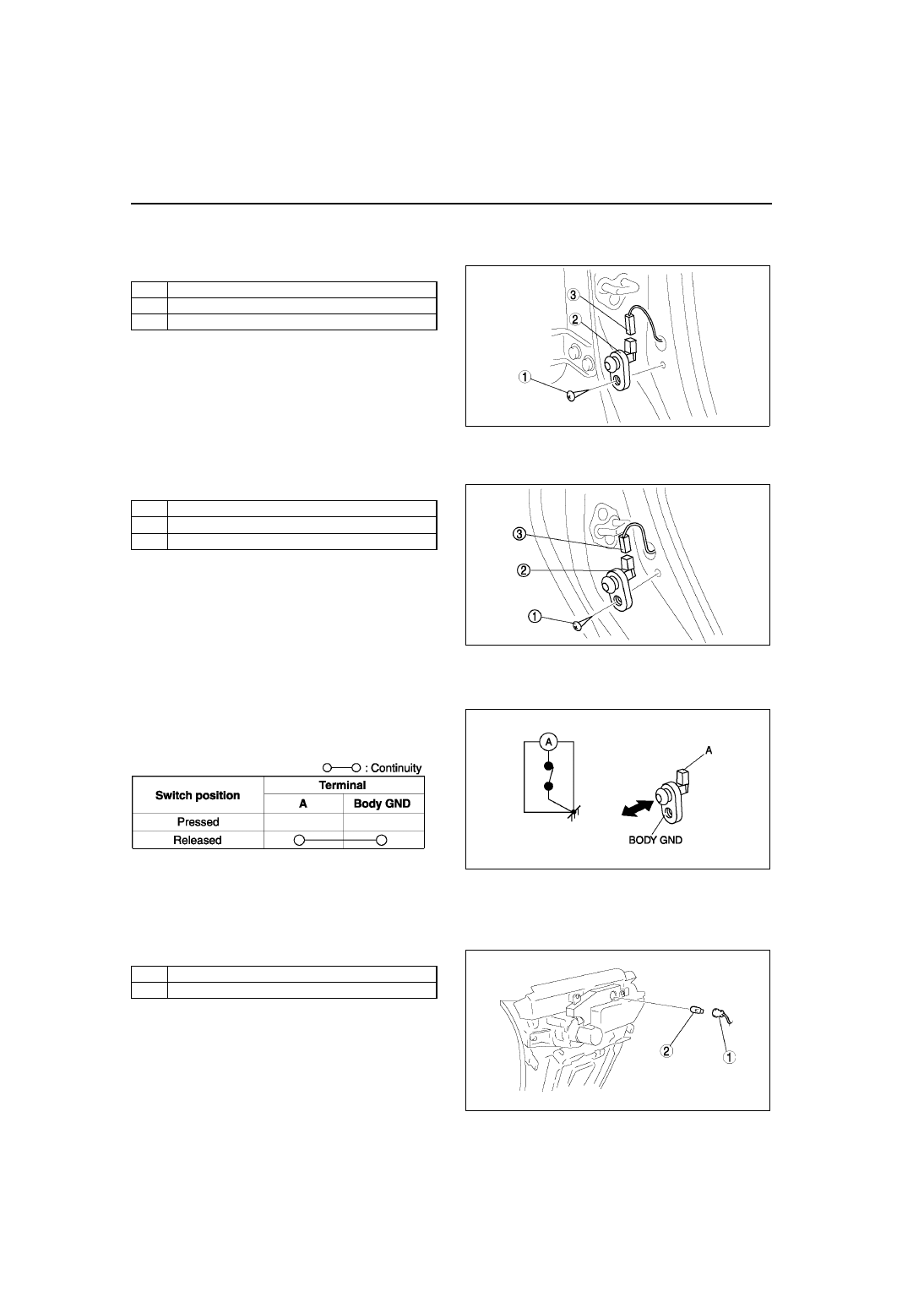
2. Inspect for continuity between the door switch 

terminal and a body ground using an ohmmeter.

• If not as specified, replace the door switch.

End Of Sie

ASHTRAY ILLUMINATION BULB REMOVAL/INSTALLATION

A6E811455431W01

1. Disconnect the negative battery cable.
2. Remove the boot panel.
3. Remove in the order indicated in the table.

4. Install in the reverse order of removal.

1

Screw

2

Door switch

3

Connector

A6E8114W108

1

Screw

2

Door switch

3

Connector

A6E8114W109

A6E8114W115

A6E8114W122

1

Socket

2

Ashtray illumination bulb

A6E8114W106

INTERIOR LIGHTING SYSTEM 

T–53

T

End Of Sie

IGNITION KEY ILLUMINATION BULB REMOVAL/INSTALLATION

A6E811460231W01

1. Disconnect the negative battery cable.
2. Remove the column cover. (See 

S–84 COLUMN COVER REMOVAL/INSTALLATION

)

3. Remove the ignition key illumination bulb.
4. Install in the reverse order of removal.

End Of Sie

GLOVE COMPARTMENT LIGHT BULB REMOVAL/INSTALLATION

A6E811451445W01

1. Disconnect the negative battery cable.
2. Remove in the order indicated in the table.

3. Install in the reverse order of removal.

End Of Sie

PANEL LIGHT CONTROL SWITCH REMOVAL/INSTALLATION

A6E811466600W01

1. Disconnect the negative battery cable.
2. Remove in the order indicated in the table.

3. Install in the reverse order of removal.

Panel Light Control Switch Removal Note

1. Insert your hand from the lower side of the dashboard and squeeze the tabs of the panel light control switch.
2. Pull the panel light control switch forward to remove it.

End Of Sie

A6E8114W129

1

Socket 

2

Glove compartment light bulb

A6E8114W113

1

Panel light control switch (See 

T–53 Panel Light 

Control Switch Removal Note

)

2

Connector

A6E8114W116

T–54

INTERIOR LIGHTING SYSTEM 

PANEL LIGHT CONTROL SWITCH INSPECTION

A6E811466600W02

1. Connect the connector to the panel light control switch.
2. Connect the negative battery cable.
3. Measure the voltage at the panel light control switch using voltmeter.

• When inspecting terminal B for continuity, disconnect the panel light control switch connector.

4. If the value are not as specified in the Terminal Voltage List (Reference), inspect the parts under “Action” and 

related wiring harnesses.

5. If the system does not work properly even though the parts or related wiring harnesses do not have any 

malfunction, replace the panel light control switch.

Terminal Voltage Table (Reference)

Terminal

Signal

Connected to

Test condition

Voltage (V)/

Continuity

Action

A

TNS (Without 
running light 
system)

TNS relay

Headlight switch at TNS or headlight 
position

B+

• Inspect TNS 

relay (See 

T–24 

RELAY 
INSPECTION

)

• Inspect ILLUMI 

10A fuse

• Inspect related 

harness

Other

0

Running light 
(With running 
light system)

Running light unit

Headlight switch at TNS or headlight 
position

B+

• Inspect running 

light unit 
(See 

T–46 

RUNNING LIGHT 
UNIT 
INSPECTION

)

• Inspect related 

harness

Other

0

C

Illumination

Each illumination

Inspect using an oscilloscope (See 

T–

55 Terminal C inspection

)

• Inspect each 

illumination

• Inspect related 

harness

B

Ground

GND

Under any condition: inspect for 
continuity to ground

Yes

• Inspect GND

• Inspect related 

harness

A6E8114W123

INTERIOR LIGHTING SYSTEM 

T–55

T

Terminal C inspection

1. Measure the wave pattern of the terminal C on 

the panel light control switch using an 
oscilloscope.

2. Set the headlight switch to either the TNS or 

headlight position.

3. Set the panel light control switch to the brightest 

position.

4. Verify that the pattern on the screen is as shown 

in the figure.

5. Verify that the pattern on the screen matches the 

pattern shown in the figure as the panel light 
control switch is gradually turned to the darkest 
position.

End Of Sie

A6E8114W124

A6E8114W125

A6E8114W126


Content   ..  321  322  323  324   ..