Mazda 6. Manual - part 318


  Index      Mazda     Mazda 6 - service repair manual 2002 year


Search            


Content   ..  316  317  318  319   ..


Mazda 6. Manual - part 318


T–32

EXTERIOR LIGHTING SYSTEM 

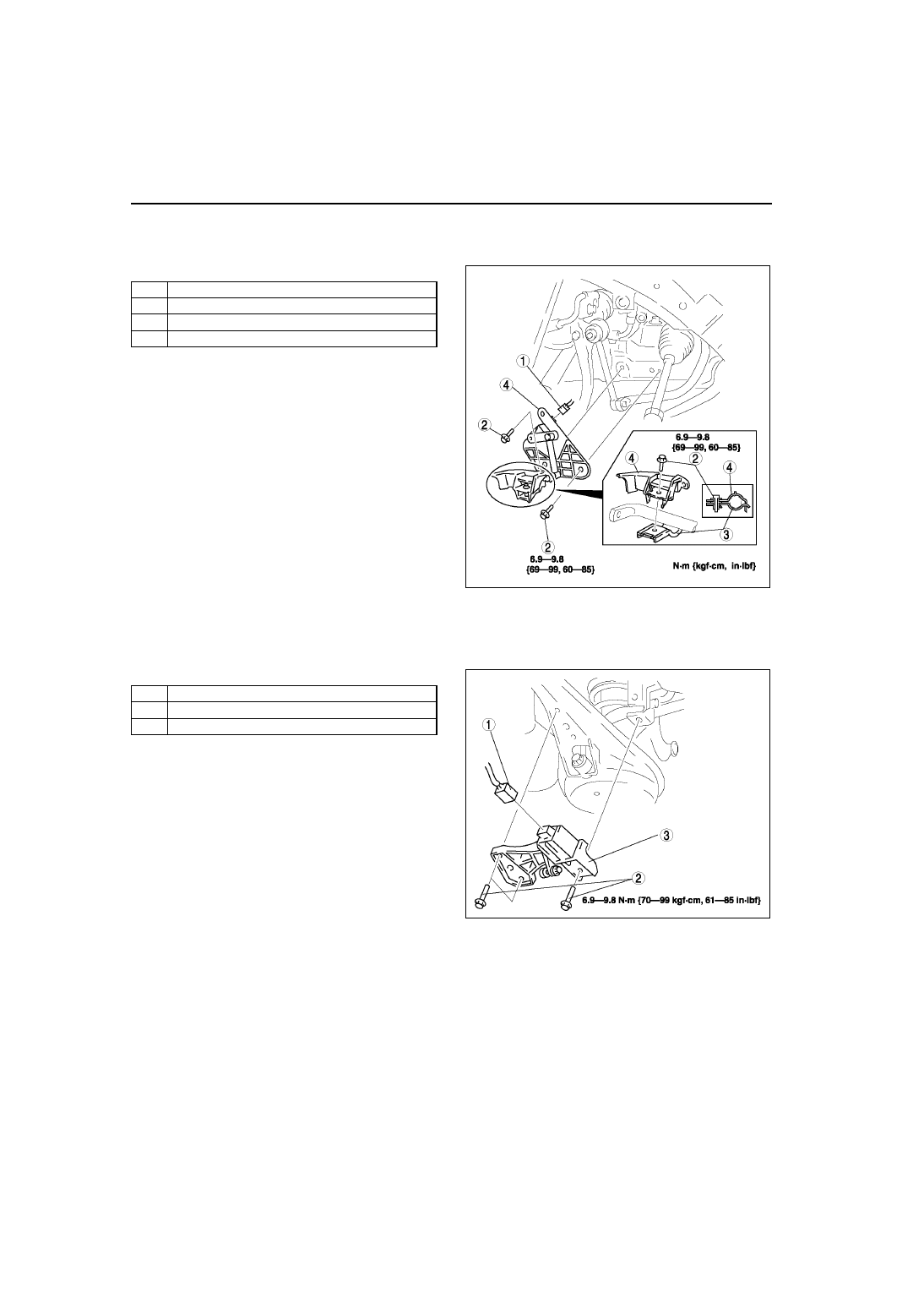
FRONT AUTO LEVELING SENSOR REMOVAL/INSTALLATION

A6E811251030W06

1. Disconnect the negative battery cable.
2. Jack up the vehicle and remove the wheel and tire.
3. Remove in the order indicated in the table.

4. Install in the reverse order of removal.
5. Adjust the headlight zeroset. (See 

T–31 

HEADLIGHT ZEROSET

)

End Of Sie

REAR AUTO LEVELING SENSOR REMOVAL/INSTALLATION

A6E811251030W07

1. Disconnect the negative battery cable.
2. Jack up the vehicle.
3. Remove in the order indicated in the table.

4. Install in the reverse order of removal.
5. Adjust the headlight zeroset. (See 

T–31 

HEADLIGHT ZEROSET

)

End Of Sie

1

Connector

2

Bolt

3

Bracket

4

Front auto leveling sensor

A6E8112W165

1

Connector

2

Bolt

3

Rear auto leveling sensor

A6E8112W156

EXTERIOR LIGHTING SYSTEM 

T–33

T

PARKING LIGHT BULB REMOVAL/INSTALLATION

A6E811251040W01

1. Disconnect the negative battery cable.
2. Remove in the order indicated in the table.

3. Install in the reverse order of removal.

End Of Sie

FRONT TURN LIGHT REMOVAL/INSTALLATION

A6E811251050W01

1. Disconnect the negative battery cable.
2. Remove in the order indicated in the table.

.

3. Install in the reverse order of removal.

End Of Sie

FRONT SIDE TURN LIGHT REMOVAL/INSTALLATION

A6E811268370W01

1. Disconnect the negative battery cable.
2. Remove in the order indicated in the table.

3. Install in the reverse order of removal.

End Of Sie

1

Cover

2

Socket

3

Parking light bulb

A6E8112W109

1

Socket

2

Front turn light bulb

A6E8112W110

1

Front side turn light

2

Connector

A6E8112W127

T–34

EXTERIOR LIGHTING SYSTEM 

FRONT FOG LIGHT AIMING

A6E811251680W01

1. Adjust the tire air pressure to the specification.
2. Position the unloaded vehicle on a flat, level surface.
3. Seat one person in the driver’s seat.
4. Position the vehicle 3 m {10 ft} in front of a white 

screen.

5. While adjusting one fog light, mask the other.
6. Start the engine to charge the battery.
7. Turn the front fog light on.

8. Adjust the front fog light by turning the adjusting 

screws as shown in the figure. Loosen the screws 
first, then tighten them.

Note

• If the adjusting screws are tightened first, 

then loosened, they will continue to loosen 
when the vehicle is in motion and may cause 
the front fog lights to become misaligned.

End Of Sie

FRONT FOG LIGHT BULB REMOVAL/INSTALLATION

A6E811251680W02

1. Disconnect the negative battery cable.
2. Remove in the order indicated in the table.

Caution

• A halogen bulb generates extremely high 

heat when it is used. If the surface of the 
bulb is soiled, excessive heat will build 
up and the light’s life will be shortened. 
When replacing the bulb, hold the metal 
flange, not the glass.

3. Install in the reverse order of removal.

Front Fog Light Bulb Removal Note

1. Release the bulb pressing wire to remove the front fog light bulb.

End Of Sie

A6E8112W157

A6E8112W117

A6E8112W137

1

Cover

2

Connector

3

Front fog light bulb (See 

T–34 Front Fog Light Bulb 

Removal Note

)

A6E8112W111

EXTERIOR LIGHTING SYSTEM 

T–35

T

REAR COMBINATION LIGHT REMOVAL/INSTALLATION

A6E811251150W01

1. Disconnect the negative battery cable.
2. Remove the trunk side trim. (See 

S–92 TRUNK SIDE TRIM REMOVAL/INSTALLATION

)

3. Remove in the order indicated in the table.

4. Install in the reverse order of removal.

End Of Sie

INBOARD COMBINATION LIGHT REMOVAL/INSTALLATION

A6E811251380W01

1. Disconnect the negative battery cable.
2. Remove the trunk lid trim (liftgate lower trim). (See 

S–93 TRUNK LID TRIM REMOVAL/INSTALLATION

) (See 

S–95 LIFTGATE LOWER TRIM REMOVAL/INSTALLATION

)

3. Remove in the order indicated in the table.

4. Install in the reverse order of removal.

Inboard Combination Light Installation Note

1. Insert the inboard combination light into the trunk 

lid (liftgate) as shown in the figure, then pivot it 
inward and fix in place.

1

Connector

2

Bolt

3

Rear combination light

4

Socket

5

Rear turn light bulb

6

Brake light/taillight bulb

A6E8112W118

1

Connector

2

Nut

3

Inboard combination light (See 

T–35 Inboard 

Combination Light Installation Note

)

4

Socket

5

Back-up light bulb

6

Rear fog light bulb (L.H.D.: left side only, R.H.D.: 
right side only)

A6E8112W119

A6E8112W120


Content   ..  316  317  318  319   ..