Mazda 6. Manual - part 285
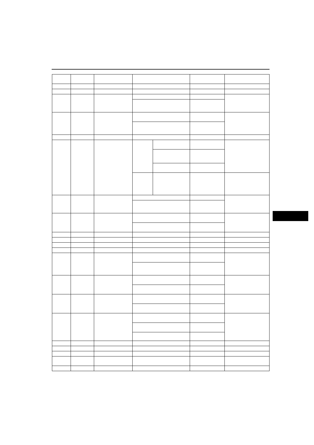
POWER DOOR LOCK SYSTEM
S–35
S
*1
: Vehicles with double locking system
*2
: Vehicles with theft-deterrent system
2D
-
-
-
-
-
2E
-
-
-
-
-
2F
Key
reminder
switch
Key reminder switch
Key reminder switch at on
B+
• Inspect key reminder
switch
• Inspect related
harness
Other
Below 1.0
2G
Liftgate
open/closed
Door switch
Lliftgate is open (cargo
compartment light switch is on)
Below 1.0
• Inspect cargo
compartment light
switch
• Inspect related
harness
Liftgate are closed (cargo
compartment light switch are off)
B+
2H
-
-
-
-
-
2I
Hazard
Flasher unit
Except
vehicles
with theft-
deterrent
system
Transmitter LOCK
button is pressed
B+
→Below
1.0
→B+
• Inspect flasher unit
• Inspect related
harness
Transmitter
UNLOCK button is
pressed
B+
→Below
1.0
→B+→Below
1.0
→B+
No transmitter
buttons are pressed
B+
Vehicles
with theft-
deterrent
system
Under any condition
B+
• Inspect theft-
deterrent control
module
• Inspect related
harness
2J
*1
Security
light output
Instrument cluster
Double locking system operated
1.4
• Inspect instrument
cluster
• Inspect related
harness
Other
B+
2K
Door open/
closed
Door switch
Any door is open (any door
switch is on)
Below 1.0
• Inspect door
switches
• Inspect related
harness
All door are closed (door
switches are off)
B+
2L
-
-
-
-
-
2N
-
-
-
-
-
2M
-
-
-
-
-
2O
-
-
-
-
-
2P
*2
Theft-
deterrent
alarm
control
Theft-deterrent
control module
Ignition switch is at ON position
B+
→Below
1.0
→B+
• Inspect theft-
deterrent control
module
• Inspect related
harness
Other
B+
2Q
Lock input
Door lock-link switch
Driver’s side door is locked:
inspect for continuity to ground
Yes
• Inspect door lock-link
switch
• Inspect related
harness
Driver’s side door is unlocked:
inspect for continuity to ground
No
2R
Unlock input Door lock-link switch
Driver’s side door is locked:
inspect for continuity to ground
No
• Inspect door lock-link
switch
• Inspect related
harness
Driver’s side door is unlocked:
inspect for continuity to ground
Yes
2S
Lock/Unlock
input
• Door key cylinder
switch (driver’s
side)
*1
• Door key cylinder
switch
(passenger’s side)
At the moment of key cylinder is
locked
Approx. 2.5
• Inspect key cylinder
switch
• Inspect related
harness
At the moment of key cylinder is
unlocked
Below 1.0
Key cylinder at neutral position
Approx. 5
2T
-
-
-
-
-
2U
-
-
-
-
-
2V
-
-
-
-
-
2W
Signal
ground
GND
Under any condition: inspect for
continuity to ground
Yes
• Inspect GND
2X
-
-
-
-
-
Terminal
Signal
Connected to
Test condition
Voltage (V)/
Continuity
Action