Mazda 6. Manual - part 241


  Index      Mazda     Mazda 6 - service repair manual 2002 year


Search            


Content   ..  239  240  241  242   ..


Mazda 6. Manual - part 241


P–22

CONVENTIONAL BRAKE SYSTEM 

End Of Sie

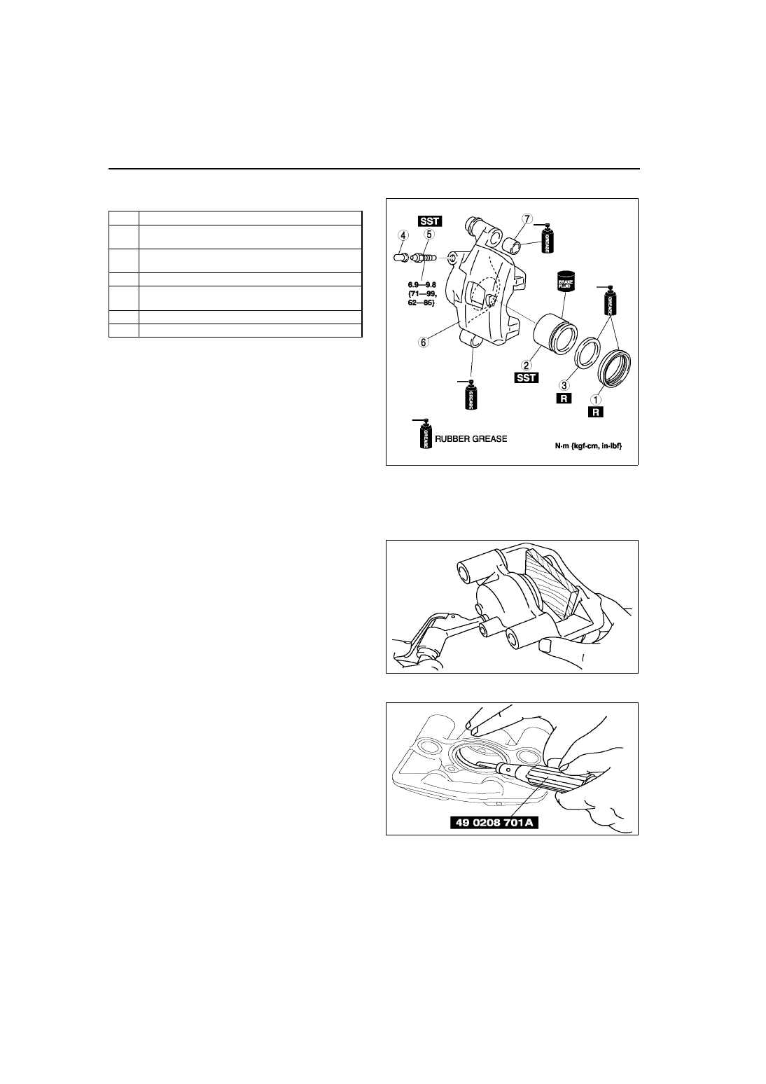
CALIPER (FRONT) DISASSEMBLY/ASSEMBLY

A6E691233990W01

1. Disassemble in the order indicated in the table.

2. Assemble in the reverse order of removal.

Piston Disassembly Note

Caution

• Blow the compressed air slowly to prevent the piston from suddenly popping out.

1. Place a piece of wood in the caliper, then blow 

compressed air through the hole to force the 
piston out of the caliper.

Piston Seal Disassembly Note

1. Remove the piston seal from the brake caliper 

using the SST.

1

Dust seal

2

Piston
(See 

P–22 Piston Disassembly Note

)

3

Piston  seal
(See 

P–22 Piston Seal Disassembly Note

)

4

Bleeder cap

5

Bleeder screw
(See 

P–23 Bleeder Screw Assembly Note

)

6

Caliper body

7

Boot

A6E6912W046

A6E6912W047

A6E6912W048

CONVENTIONAL BRAKE SYSTEM 

P–23

P

Bleeder Screw Assembly Note

1. Assemble the bleeder screw to the caliper using 

the SST.

Tightening torque

6.9—9.8 N·m {71—99 kgf·cm, 62—86 in·lbf}

End Of Sie

REAR BRAKE (DISC) INSPECTION

A6E691226980W01

Brake Judder Repair Hint

1. (See 

P–17 FRONT BRAKE (DISC) INSPECTION

.)

Disc Plate Thickness Inspection

Caution

• Excessive runout may result if the disc plate is removed from the vehicle then machined. Machine 

the disc plate while installed on the vehicle.

1. Measure the thickness of the disc plate.

• If the thickness is not within the specification, replace the disc plate.

Minimum

8 mm {0.31 in}

Minimum thickness after machining using a brake lathe on-vehicle

8.8 mm {0.35 in}

Disc Pad Thickness Inspection

1. Jack up the front of the vehicle and support it with safety stands.
2. Remove the wheel and tires.
3. Verify the remaining thickness of the pads.

Minimum thickness

2.0 mm {0.079 in} min.

4. Replace the pads as a set: right and left wheels, if 

either one is at or less than the minimum 
thickness.

End Of Sie

A6E6912W049

X3U411WAS

P–24

CONVENTIONAL BRAKE SYSTEM 

REAR BRAKE (DISC) REMOVAL/INSTALLATION

A6E691226980W02

1. Remove in the order indicated in the table.
2. Install in the reverse order of removal.
3. After installation, depress the pedal several times, rotate the wheel by hand, and verify that the brake does not 

drag.

.

A6A6912W008

9

7

7

5

4

3

1

2

10

6

8

8

6

SST

SST

R

51.0—66.7 {5.21—6.80, 37.7—49.1}

21.6—29.4 {2.21—2.99, 16.0—21.6}

37.3—49.0
{3.81—4.99, 27.6—36.1}

 N·m {kgf·m, ft·lbf}

9.8—14.7 N·m 
{100—149 kgf·cm, 
87—130 in·lbf}

GREASEGREASE

RUBBER GREASE

1

Parking brake cable, clip

2

Flexible hose

3

Bolt

4

Caliper

5

Spring

6

Disc  pad
(See 

P–25 Disc Pad Installation Note

)

7

Shim

8

Guide plate

9

Mounting support

10

Disc plate
(See 

P–20 Disc Plate Removal Note

)

(See 

P–20 Disc Plate Installation Note

)

CONVENTIONAL BRAKE SYSTEM 

P–25

P

Disc Pad Installation Note

1. Push the piston fully inward using the SST.
2. Install the disc pads.

End Of Sie

DISC PAD (REAR) REPLACEMENT

A6E691226630W01

1. Remove in the order indicated in the table.
2. Install in the reverse order of removal.

.

End Of Sie

49 FA18 602

A6E6912W039

A6A6912W009

 N·m {kgf·m, ft·lbf}

37.3—49.0
{3.81—4.99, 27.6—36.1}

2

3

4

6

5

5

6

1

7

7

GREASEGREASE

RUBBER GREASE

SST

SST

1

Parking brake cable, clip

2

Screw plug

3

Lock  bolt

4

Disc pad
(See 

P–25 Disc Pad Installation Note

)

5

Shim

6

Guide plate


Content   ..  239  240  241  242   ..