Mazda 6. Manual - part 239


  Index      Mazda     Mazda 6 - service repair manual 2002 year


Search            


Content   ..  237  238  239  240   ..


Mazda 6. Manual - part 239


P–14

CONVENTIONAL BRAKE SYSTEM 

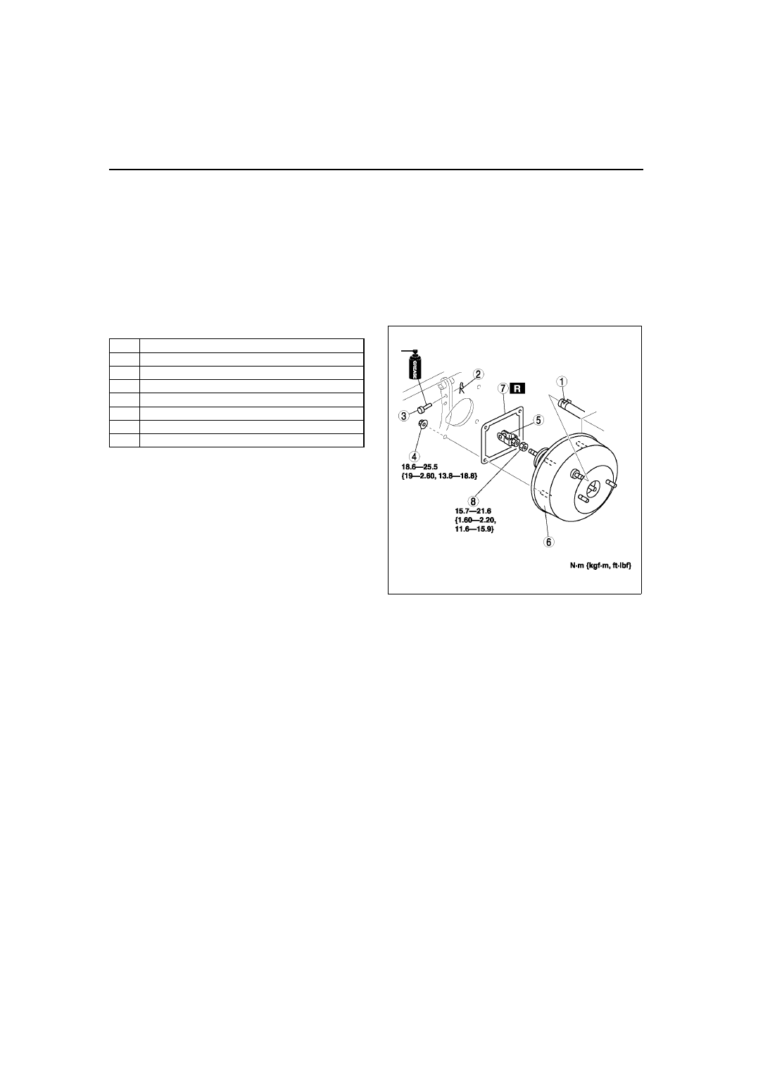
POWER BRAKE UNIT REMOVAL/INSTALLATION

A6E691243800W02

1. Remove the master cylinder. (See 

P–10 MASTER CYLINDER REMOVAL/INSTALLATION

.)

2. Remove the wiper arm. (See 

T–57 WINDSHIELD WIPER ARM AND BLADE REMOVAL/INSTALLATION

.)

3. Remove the cowl grille. (See 

S–50 COWL GRILLE REMOVAL/INSTALLATION

.)

4. Remove the wiper motor. (See 

T–56 WINDSHIELD WIPER MOTOR REMOVAL/INSTALLATION

.)

5. Remove the cowl panel. (See 

S–119 COWL PANEL REMOVAL/INSTALLATION

.)

6. For L.H.D., remove the A/C bracket.
7. For L.H.D., remove the ABS/TCS HU/CM or DSC HU/CM . (See 

P–28 ABS (ABS/TCS) HU/CM REMOVAL/

INSTALLATION

.) (See 

P–38 DSC HU/CM REMOVAL/INSTALLATION

.

8. For R.H.D., remove the alternator cover.
9. For R.H.D., remove the insulator.

10. For R.H.D., remove the vacuum pipe bracket.
11. Remove in the order indicated in the table.

12. Install in the reverse order of removal.

End Of Sie

POWER BRAKE UNIT INSPECTION

A6E691243800W01

Warning

• The following inspection methods are the simple inspection methods to judge the function of 

power brake.

• If there is malfunction in power brake unit, replace the power brake unit as a component.

Power Brake Unit Function Check (Simple Method)
Step 1

1. With the engine stopped, depress the pedal a few times.
2. With the pedal depressed, start the engine.
3. If the pedal moves down slightly immediately after the engine starts, the unit is operating.

Step 2

1. Start the engine.
2. Stop the engine after it has run for 1 or 2 minutes.
3. Depress the pedal with the usual force.
4. If the first pedal stroke is long and becomes shorter with subsequent strokes, the unit is operating.

• If a problem is found, inspect for damage of the vacuum hose, and vacuum tank. Repair if necessary, and 

inspect it again.

Step 3

1. Start the engine.
2. Depress the pedal with usual force.
3. If the pedal height does not change, the unit is operating.
4. Hold the pedal down for about 30 seconds.
5. If the pedal height does not change, the unit is operating.

1

Vacuum hose

2

Snap pin

3

Clevis pin

4

Nut

5

Fork

6

Power brake unit

7

Gasket

8

Nut

A6E6912W044

CONVENTIONAL BRAKE SYSTEM 

P–15

P

Power Brake Unit Function Check (Inspection Using The Testers)

1. Connect the SSTs, vacuum gauge, and pedal 

depression force gauge as shown in the figure to 
bleed the air from SSTs and brake line. (Bleed the 
air from SSTs using a air bleed valve A.)

Checking for vacuum loss (unloaded condition)

1. Stop the engine when the vacuum gauge reading reaches 66.7 kPa {500 mmHg, 19.7 inHg}.
2. Observe the vacuum gauge for 15 seconds.

• If the gauge shows 63.3—66.7 kPa {475—500 mmHg, 18.7—19.6 inHg}, the unit is operating.

• If not, inspect for damage on the check valve or vacuum hose, and examine the installation. Repair as 

necessary, and inspect it again.

Checking for vacuum loss (loaded condition)

1. Start the engine.
2. Depress the brake pedal with a force of 196 N {20 kgf, 44 lbf}.
3. Stop the engine when the vacuum gauge reading reaches 66.7 kPa {500 mmHg, 19.7 inHg}.
4. Observe the vacuum gauge for 15 seconds.
5. If the gauge shows 63.3—66.7 kPa {475—500 mmHg, 18.7—19.6 inHg}, the unit is operating.

Checking for hydraulic pressure

1. When the engine is stopped (vacuum 0 kPa {0 mmHg, 0 inHg}) and the fluid pressure is within the 

specification, the unit is operating.

2. Start the engine. Depress the brake pedal when the vacuum reaches 66.7 kPa {500 mmHg, 19.7 inHg}.

• If the fluid pressure is within the specification, the unit is operating.

• If the fluid pressure is not as specified, inspect for damage to the check valve or vacuum hose, and fluid 

leakage of the hydraulic line. Repair as necessary, and inspect again.

End Of Sie

A6E6912W005

Pedal force

Fluid pressure

200 N {20 kgf, 44 lbf}

588 kPa {5.95 kgf/cm

2

, 84.7 psi} 

min.

Pedal force

Fluid pressure

200 N {20 kgf, 44 lbf}

8,787 kPa {89.60 kgf/cm

2

1,274 psi} min.

P–16

CONVENTIONAL BRAKE SYSTEM 

DUAL PROPORTIONING VALVE INSPECTION (WITHOUT ABS)

A6E691243900W01

1. Connect the SSTs to the brake pipes as shown in 

the figure.

2. Bleed the air from the brake system.
3. Measure the fluid pressure of the master cylinder 

and the rear brake.

• If not within the specification, replace the dual 

proportioning valve.

Fluid pressure

kPa {kgf/cm

2

, psi}

End Of Sie

DUAL PROPORTIONING VALVE REPLACEMENT (WITHOUT ABS)

A6E691243900W02

1. Remove in the order indicated in the table.

2. Install in the reverse order of removal.

A6E6912W006

A6E6912W007

A

A'

B

B'

2,450 {25, 355}

2,450 {25, 355} 

± 200 {2, 29}

5,880 {60, 853}

3,480 {35.5, 505} 

± 300 {3, 44}

1

Brake pipe

2

Bolt

3

Dual proportioning valve 
(See 

P–17 Dual Proportioning Valve Installation 

Note

)

A6E6912W035

CONVENTIONAL BRAKE SYSTEM 

P–17

P

Dual Proportioning Valve Installation Note

1. Install the dual proportioning valve so that the R 

mark faces the left side of the vehicle.

End Of Sie

FRONT BRAKE (DISC) INSPECTION

A6E691233980W01

Brake Judder Repair Hint
Description

1. Brake judder concern has the following 3 characteristics:

Steering wheel vibration

1. Steering wheel vibrates in the direction of its rotation. This characteristic is most noticeable when applying 

brakes at a vehicle speed of 100—140 km/h {62.1—86.8 mph}.

Floor vibration

1. When applying brakes, the vehicle body shakes back and forth. The seriousness of shake is not influenced by 

vehicle speed.

Brake pedal vibration

1. When applying brakes, a pulsating force tries to push the brake pad back occurs. The pulsation is transmitted 

to the brake pedal.

2. The following are the main possible causes of brake judder:

Due to an excessive runout (side-to-side wobble) of disc plate, the thickness of disc plate is uneven.

1. If the runout is more than 0.05 mm {0.002 in} to 10 mm {0.39 in} from the disc plate edge, an uneven wear 

occurs on the disc plate because the pad contacts the plate unevenly.

2. If the runout is less than 0.05 mm {0.002 in}, uneven wear does not occur.

The disc plate is deformed by heat.

1. Repeated panic braking may raise the temperature in some portions of disc plate by approximately 1,000 

°

{1,832 

°F}. This results in deformed disc plate.

Due to corrosion, the thickness and friction coefficient of disc plate change.

1. If a vehicle is parked under damp conditions for a long time, corrosion occurs on the friction surface of disc 

plate.

2. The thickness of corrosion is uneven and sometimes appears like a wave pattern, which changes the friction 

coefficient and causes a reaction force.

A6E6912W045


Content   ..  237  238  239  240   ..