Mazda 6. Manual - part 226
M–14
DRIVE SHAFT
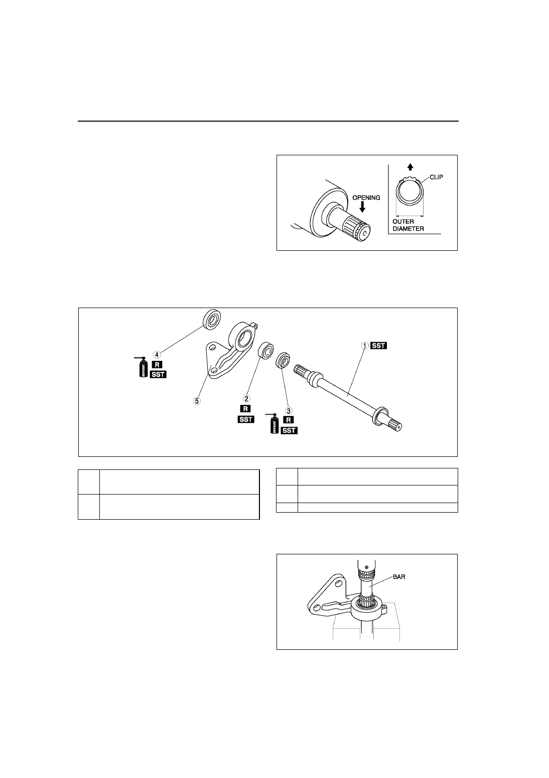
Clip Installation Note
1. Install a new clip onto the joint shaft with the opening facing upward. Ensure that the diameter of the clip does
not exceed the specification on installation.
2. After installation, measure the outer diameter. If it
exceeds the specification, repeat Step 1 using a
new clip.
Outer diameter specification
31.2 mm {1.23 in} max.
End Of Sie
JOINT SHAFT DISASSEMBLY/ASSEMBLY
A6E631625700W03
1. Disassemble in the order indicated in the table.
2. Assemble in the reverse order of disassembly.
Joint Shaft Disassembly Note
1. Disassemble the joint shaft.
A6E0313W021
A6E0313W026
1
Joint shaft
(See
M–14 Joint Shaft Disassembly Note
(See
M–16 Joint Shaft Assembly Note
2
Bearing
(See
(See
3
Dust seal (Left)
(See
M–16 Dust Seal (Left) Assembly Note
)
4
Dust seal (Right)
(See
M–15 Dust Seal (Right) Assembly Note
)
5
Bracket
A6E0313W052