Mazda 6. Manual - part 136
F–66
ON-BOARD DIAGNOSTIC
DTC CONFIRMATION PROCEDURE
A6E397018881W11
End Of Sie
KOEO/KOER SELF-TEST
A6E397018881W12
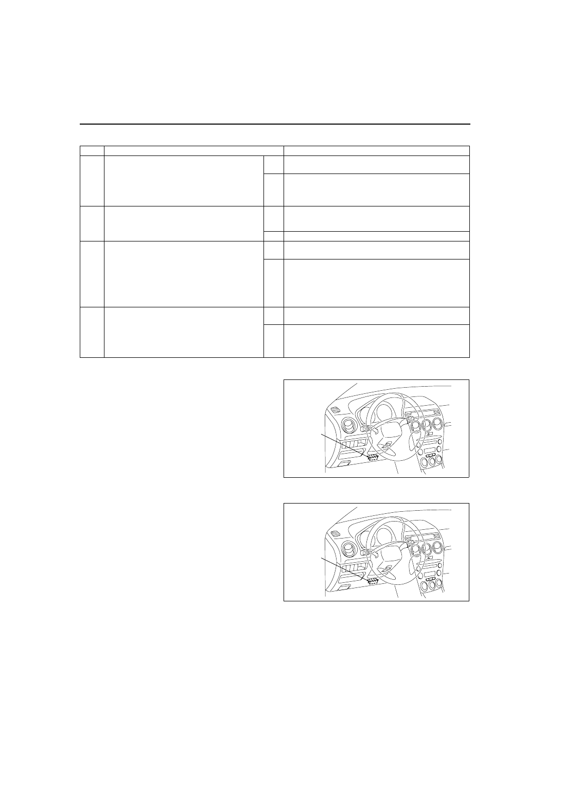
1. Connect WDS or equivalent to the vehicle DLC-2
16-pin connector located as shown in the figure.
2. Perform KOEO/KOER self-test.
End Of Sie
AFTER REPAIR PROCEDURE
A6E397018881W13
1. Connect WDS or equivalent to the vehicle DLC-2
16-pin connector located as shown in the figure.
2. Turn the ignition key from OFF to ON.
3. Record DTC if retrieved.
4. Erase all diagnostic data by WDS or equivalent.
End Of Sie
STEP
INSPECTION
ACTION
1
RECORD CONTINUOUS MEMORY DTC AND
FREEZE FRAME DATA
• Turn ignition key to ON (Engine OFF).
• Connect WDS or equivalent to DLC.
• Retrieve all stored DTCs.
• Are there any DTCs present?
Yes Record all stored DTCs (Continuous Memory DTC) and
Freeze Frame Data on repair order, then go to next step.
No
Go to next step.
2
VERIFY RELATED REPAIR INFORMATION
• Check for related Service information
availability.
• Is any related repair information available?
Yes Perform repair or diagnosis according to available Service
information.
• If vehicle is not repaired, go to next step.
No
Go to next step.
3
PERFORM KEY ON ENGINE OFF (KOEO)
SELF-TEST
• Start engine.
• Warm up engine completely.
• Turn off all electrical loads.
• Perform KOEO SELF-TEST PROCEDURE.
)
• Are there any KOEO DTCs present?
Yes Repair KOEO DTC.
(See
)
No
Go to next step.
4
PERFORM KEY ON ENGINE RUNNING (KOER)
SELF-TEST
• Start engine.
• Perform KOER SELF-TEST PROCEDURE.
)
• Are there any KOER DTCs present?
Yes Repair KOER DTC.
(See
No
• If Continuous Memory DTC is present at Step 1, return
to applicable DTC troubleshooting procedure step.
• If Continuous Memory DTC is not present at Step 1, go
to symptom troubleshooting.
DLC-2
A6E3970W002
DLC-2
A6E3970W002