Mazda 6. Manual - part 79
T–92
AIR BAG SYSTEM
PASSENGER-SIDE AIR BAG MODULE
A6E813057050T01
Outline
•
A dual inflator, 1 inflator divided into 2, has been adopted in accordance with the front air bag system 2-step
deployment control.
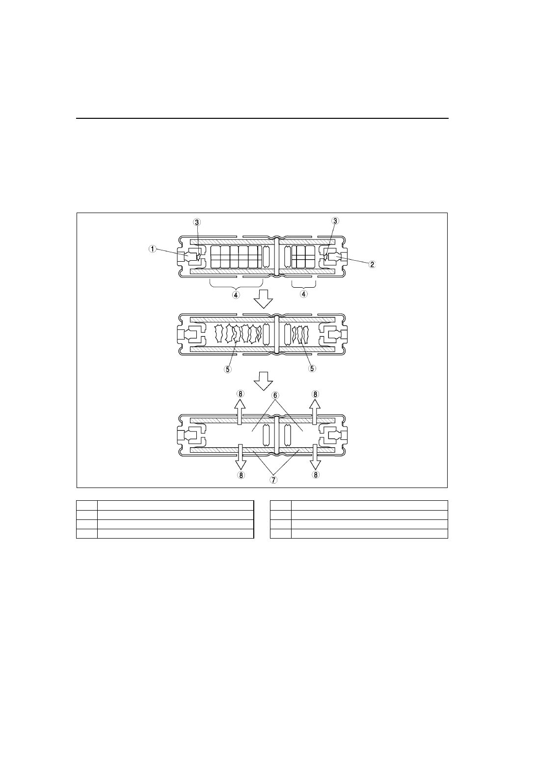
Inflator Operation
1. The igniter built into the inflator begins to build up heat when the operation (deployment) signal is sent from the
SAS unit. The inflammation agent is ignited by the build up of heat of the igniter.
2. The ignition of the inflammation agent causes the combustion of an agent which releases nitrogen gas.
3. The nitrogen gas is cooled at the filter, and the filtrate is injected to the air bag.
.
End Of Sie
A6E8130T008
1
Ignitor (inflator No.1)
2
Ignitor (inflator No.2)
3
Ignition of inflammation agent
4
Gas generating agent
5
Gas generating agent combustion
6
Nitrogen gas
7
Filter
8
To air bag