Mazda 6. Manual - part 44


  Index      Mazda     Mazda 6 - service repair manual 2002 year


Search            


Content   ..  42  43  44  45   ..


Mazda 6. Manual - part 44


ON-BOARD DIAGNOSTIC 

P–19

P

Fail-safe Function

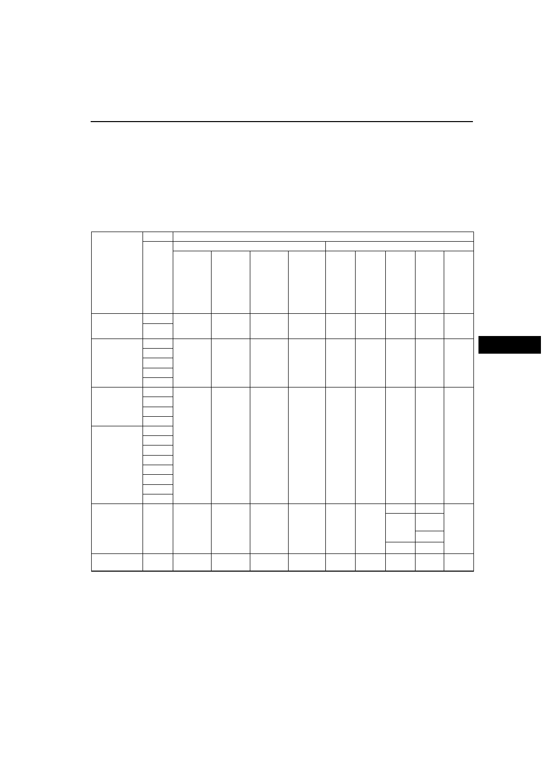
If a failure is detected in the self-diagnostic function, the fail-safe illuminates the ABS warning light, BRAKE 
system warning light, DSC indicator light, and/or TCS (DSC) OFF light to notify the driver. At the same time, the 
ABS (ABS/TCS) or DSC HU/CM controls the ABS, EBD, TCS, DSC and brake assist. The fail-safe function 
ensures normal braking even when ABS, EBD, TCS, DSC and/or brake assist control stops, as shown in the 
figure.

Caution

In the event that EBD control stops, the rear wheels may lock before the front wheels, causing the 
vehicle to skid. Inspect the system immediately if EBD control stops.

Fail-safe function table

Malfunction 

location

DTC

Fail-safe function

WDS 

or 

equival

ent

Warning light illumination condition

Control condition

ABS 

warning 

light

BRAKE 

system 

warning 

light 

(when 

parking 

brake is 

released)

DSC (TCS) 

indicator 

light

DSC 

(TCS) 

OFF light

ABS 

control

EBD 

control

TCS 

control

DSC 

control

Brake 
assist 

control

Brake fluid 
pressure 
sensor

C1953

Not 

illuminated

Not 

illuminated

Illuminated

Not 

illuminated

Availa-

ble

Availa-

ble

Availa-

ble

Stop

Stop

C1954

Combine 
sensor

C1280

Not 

illuminated

Not 

illuminated

Illuminated

Not 

illuminated

Availa-

ble

Availa-

ble

Availa-

ble

Stop

Availa-

ble

C1730

C1951

C1952

C1959

Wheel-speed 
sensor

C1145

Illuminated

*1

Not 

illuminated 

*1, 2

Illuminated

*1

Illuminated

*1

Stop

Availa-

ble 

*3

Stop

Stop

Stop

C1155

C1165

C1175

Wheel-speed 
sensor/sensor 
rotor

C1148

C1158

C1168

C1178

C1233

C1234

C1235

C1236

Engine control 

system, engine 

speed signal 

line

C1119

Not 

illuminated

Not 

illuminated

Illuminated

Not 

illuminated

*22

Availa-

ble

Availa-

ble

Stop

Stop

Availa-

ble

Availa-

ble

Availa-

ble

Stop

*23

Stop*

24

Stop*

25

Engine coolant 
temperature

U2021

Not 

illuminated

Not 

illuminated

Not 

illuminated

Illuminated

Availa-

ble

Availa-

ble

Stop

*5

Stop

Availa-

ble

P–20

ON-BOARD DIAGNOSTIC 

Solenoid valve

C1194

Illuminated

*6, 7

Illuminated

*7, 8

Illuminated

*6

Not 

illuminated

Stop

*9

Stop

*10

Stop

*14

Stop

Stop

C1198

C1210

C1214

C1242

C1246

C1250

C1254

C1400

C1410

C1957

C1958

DSC HU/CM 
(pump)

C1140

Illuminated

Not 

illuminated

Illuminated

*22

Not 

illuminated

Stop

Availa-

ble 

Stop

*14

Stop

Stop

Solenoid valve, 
ABS motor or 
ABS wheel-
speed sensor/
sensor rotor

C1510

Not 

illuminated

*2

Illuminated

Availa-

ble 

*3

Stop

*15

C1511

C1512

C1513

DSC control

C1507

Not 

illuminated

Not 

illuminated

Availa-

ble

Availa-

ble

C1508

Fail-safe relay

C1186

Illuminated

Illuminated

Not 

illuminated

Illuminated

Stop

Stop

Stop

*14

Stop

Stop

C1266

Not 

illuminated

Availa-

ble

ABS motor 
and/or ABS 
motor relay

C1095

Illuminated

*6

Not 

illuminated

Illuminated

*6

Not 

illuminated

Stop

Availa-

ble

Stop

*14

Stop

Stop

C1096

ABS (ABS) or 
DSC 
HU/CM

B1342

Illuminated

*12, 16

Illuminated

*12, 16

Illuminated

*12, 18

Illuminated

*18

Stop

*13, 17

Stop

*13, 17

Stop

*17

Stop

Stop

*13, 17

Power supply 
system

B1318

Illuminated Illuminated Illuminated Illuminated

Availa-

ble

Availa-

ble

Availa-

ble

Availa-

ble

Availa-

ble

DSC unit 
mismatched 
installation

C1414

Illuminated

*20

Not 

illuminated

Illuminated

*20

Illuminated Stop

*21

Availa-

ble

Stop

Stop

Stop

Steering angle 
sensor

C1955

Not 

illuminated

Not 

illuminated

Not 

illuminated

Illuminated

Availa-

ble

Availa-

ble

Availa-

ble

Stop

Availa-

ble

C1956

Brake fluid 
level sensor

C1125

Not 

illuminated

Not 

illuminated

Illuminated

Not 

illuminated

Availa-

ble

Availa-

ble

Stop

*14

Stop

Stop

Reverse signal

B1627

Not 

illuminated

Not 

illuminated

Illuminated

Not 

illuminated

Availa-

ble

Availa-

ble

Availa-

ble

Stop

Availa-

ble

Brake switch

B1483

Not 

illuminated

Not 

illuminated

Illuminated

Not 

illuminated

Availa-

ble

Availa-

ble

Availa-

ble

Availa-

ble

Stop

B1484

B1486

Module 
configuration

B2477

Not 

illuminated

Not 

illuminated

Illuminated Illuminated

Availa-

ble

Availa-

ble

Stop

Stop

Stop

CAN 
communication

U1900

Not 

illuminated

Not 

illuminated

Illuminated

Not 

illuminated

Availa-

ble

Availa-

ble

Availa-

ble

Availa-

ble

Stop

U2516

Not 

illuminated

Not 

illuminated

Illuminated Illuminated

Availa-

ble

Availa-

ble

Stop

Stop

Stop

Malfunction 

location

DTC

Fail-safe function

WDS 

or 

equival

ent

Warning light illumination condition

Control condition

ABS 

warning 

light

BRAKE 

system 

warning 

light 

(when 

parking 

brake is 

released)

DSC (TCS) 

indicator 

light

DSC 

(TCS) 

OFF light

ABS 

control

EBD 

control

TCS 

control

DSC 

control

Brake 
assist 

control

ON-BOARD DIAGNOSTIC 

P–21

P

*1

: If a malfunction was detected in the previous driving mode, the light remains illuminated until the wheel-speed 

sensor is verified to be normal.

*2

: The warning light illuminates during rear wheel malfunction.

*3

: Stops control when there is malfunction in both rear wheels.

*4

: The light will go out when engine coolant temperature rises.

*5

: When engine coolant temperature is 0

°

C {32

°

F} or less, and TCS operation is inhibited by PCM. When engine 

coolant temperature rises and TCS OFF light goes out, the system is normal.

*6

: If a malfunction was detected in the previous driving mode, the light remains illuminated until the system is 

verified to be normal when the vehicle is driven at a speed of 10 km/h {6.2 mph} or more.

*7

: The warning light does not illuminates only during stability control solenoid valve or traction switch solenoid 

valve off stuck malfunction.

*8

: The warning light illuminates during rear solenoid valves off stuck malfunction.

*9

: Control dose not stop during stability control solenoid valves or traction switch solenoid valve off stuck 

malfunction.

*10

: Control does not stop during each solenoid valves (except rear inlet solenoid valve) off stuck malfunction.

*11

: The light will go out when the failure is solved.

*12

: If malfunction is related to CAN, light does not illuminate.

*13

: If malfunction is related to CAN, system does not stop.

*14

: Engine TCS is only available

*15

: Engine TCS is only available when pressure reduction inoperation is detected.

*16

: If malfunction is related to combine sensor 0 point adjustment or configuration, light dose not illuminate.

*17

: If malfunction is related to combine sensor 0 point adjustment or configuration, system dose not stop.

*18

: If the module does not configurated, light flashes.

*19

: When engine speed malfunction is detected, brake TCS is only available.

*20

: When engine is mismatch installed, the light does not illuminate.

*21

: When engine is mismatch installed, the system does not stop.

*22

: If malfunction is related to CAN (engine speed), the light illuminates.

*23

: When engine speed signal has malfunction, only brake DSC is available.

*24

: When engine control system has malfunction, only brake TCS is available.

*25

: When engine control system has malfunction, only brake DSC is available.

P–22

ON-BOARD DIAGNOSTIC 

PID/DATA Monitor Function

This function allows access to certain data values, input signal, calculated values, and system status 
information.

PID/DATA monitor table

PID name

Input/output part

Operation/unit

(WDS or equivalent)

ABS_LAMP

ABS warning light driver output state

ON/OFF

ABSLF_ I

LF ABS pressure retention valve output state

ON/OFF

ABSLF _O

LF ABS pressure reduction valve output state

ON/OFF

ABSLR_ I

LR ABS pressure retention valve output state

ON/OFF

ABSLR_ O

LR ABS pressure reduction valve output state

ON/OFF

ABSRF_ I

RF ABS pressure retention valve output state

ON/OFF

ABSRF_ O

RF ABS pressure reduction valve output state

ON/OFF

ABSRR _I

RR ABS pressure retention valve output state

ON/OFF

ABSRR _O

RR ABS pressure reduction valve output state

ON/OFF

ABS_VOLT

System battery voltage value

VOLTAGE

BOO _ABS

Brake pedal switch input

ON/OFF

BRK_FLUID

Brake fluid level sensor input

OK/LOW

BRAKE_LAMP

BRAKE system warning light driver output state

ON/OFF

CCNTABS

Number of continuous trouble code set

Number of continuous codes

LAT ACC

Lateral-G sensor

ACCELERATION

L_DSC O

Stability control solenoid valve (LF—RR)

ON/OFF

LF_ WSPD

LF wheel-speed sensor input

KPH or MPH

LR_ WSPD

LR wheel-speed sensor input

KPH or MPH

MCYLI P

Brake fluid pressure sensor

MPA

ABSVLVRLY

ABS valve control relay

ON/OFF

ABSPMPRLY

ABS pump motor relay

ON/OFF

PMPSTAT

ABS pump motor states

ON/OFF

RF _WSPD

RF wheel-speed sensor input

KPH or MPH

RPM

PCM

RPM

RR_ WSPD

RR wheel-speed sensor input

KPH or MPH

SWA POS

Steering angle sensor

ANGLE

R_DSC O

Stability control solenoid valve (RF—LR)

ON/OFF

TC LVAL

Traction switch solenoid valve (LF—RR)

ON/OFF

TC RVAL

Traction switch solenoid valve (RF—LR)

ON/OFF

TCSOUTD

PCM

PERCENTAGE

TPI

PCM

PERCENTAGE

TRAC_SW

TCS OFF switch

ON/OFF

TRANSGR

PCM

Number of continuous codes

ACCLMTR

Fail-safe relay output state

ACCELERATION

YAW_RATE

Yaw rate sensor

PERCENTAGE


Content   ..  42  43  44  45   ..