Iveco EuroCargo (12 to 26 t). Manual - part 183
71955
ABS SYSTEM WITH EBL FUNCTION
”ABS” Anti-Lock Brake System
The system is able to avoid wheel locking, that could occur
during the braking step, under any vehicle load condition and
wheel-road bed friction coefficient condition, in order to
guarantee better braking performances and a higher vehicle
stability.
The system, controlled by an electronic unit, is activated at
start-up and automatically operates for speeds greater than
5 km/h if, following a braking, one or more wheels tend to
lock.
The ABS system is able to check the engine brake exclusion
and the divider locking (if it exists).
These components are disconnected if the trend of one or
more drive wheels to lock themselves is detected.
The reconnection automatically occurs when the ABS
system action ceases.
”EBL” (Electronic Brake Limiter) anti-skid
device
The ”EBL” function checks the rear axle wheels ”skid” by
comparing it with the front axle wheels speed.
Depending on these values, the electronic control unit
computes vehicle speed, deceleration and checks the
presence of ”skid” between rear axle wheels and front axle
wheels.
The EBL function is activated (rear ABS modulators keep the
imported pressure) when the driver applies an excessive
braking force with respect to load conditions being present
on the vehicle, in summary when skid thresholds on rear axle
and vehicle deceleration thresholds are exceeded.
Data processed by the electronic control unit are wheel
revolutions and braking pressure detected by the pressure
sensor installed upstream of rear axle ABS modulators.
Figure 60
526711
ELECTRONIC UNIT
Operation
Every channel comprises four functional circuits: the first one
is the input one, that receives analogue signals emitted by the
sensor provided on the corresponding wheel, filters them
from parasitic signals and converts them into digital
information by means of cycle length measures. Then there
is a main circuit, that consists in a microprocessor, that
processes information received by the input circuit: it has a
complex program that allows it to determine wheel
acceleration and deceleration values, and to perform the logic
combination of the various adjustment signals. If necessary it
emits two control signals, that are sent to the corresponding
electro-pneumatic valve through the third unit circuit, the
control one, to adequately adjust the braking pressure.
The fourth and last circuit finally is the safety one, that takes
care of verifying the efficiency of various system components.
If an anomaly is detected, it takes care not only to inform the
driver by turning on the suitable warning light on the
dashboard, but also to automatically disconnect the whole
ABS system leaving however the traditional braking system
in efficiency.
The electronic unit is the system brain. Its task is driving the
system solenoid valves depending on signals measured by
wheel revolutions sensors.
Figure 61
526713
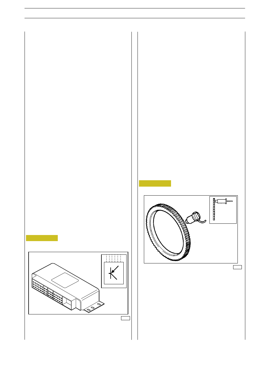
REVOLUTIONS SENSORS
526712
PHONIC WHEELS
35383
Task of revolutions sensors and phonic wheels is detecting
revolutions of their respective wheels.
Operation
The phonic wheel is housed in the wheel hub and rotates at
the same wheel speed. It generates alternate voltages by
induction in the sensors, whose frequency is proportional to
the rotation speed of the respective wheel. These voltage
signals are transmitted to the unit to be adequately
processed.
For every wheel a sensor and a phonic wheel are assembled.
This arrangement allows driving during the adjustment an
individual braking pressure for every wheel, optimising
running stability and braking space.
E
URO
C
ARGO
T
ECTOR
12-26 t
PNEUMATIC SYSTEM - BRAKES
77
Base - February 2003