Iveco EuroCargo (12 to 26 t). Manual - part 181


  Index      Iveco     Iveco EuroCargo (12 to 26 t) - service repair manual 2003 year


Search            


Content   ..  179  180  181  182   ..


Iveco EuroCargo (12 to 26 t). Manual - part 181


62580

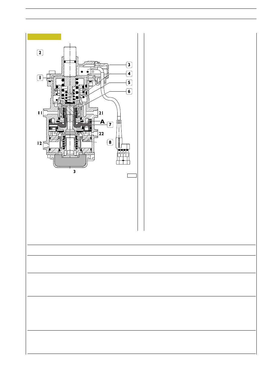
Under rest conditions, the exhaust is open, since spring (5)
pushes the pistons assembly (upper valve seat) (1 and 4)
upwards.
Valves (6 and 8) are in contact against their respective sealing
seats and intercept the passage of air between air inlet fittings
11 and 12 and outlets 21 and 22.
The lower valve seat piston (7) is at rest (running) with
discharge 3 open.
By operating on the brake pedal, control push rod (2) and
pistons assembly (1 and 4) are pushed downwards.

Piston push rod seat (4) initially closes the exhaust and
afterwards opens upper valve (6). Compressed air, from fitting
11, passes and supplies fitting 21, rear axle and chamber A.

When in section 21 and chamber A a pressure value is
reached of about 0.15

÷ 0.3 bar, valve (8) is also opened due

to the piston thrust effect.

Piston (7) abuts on valve (8), closes the exhaust and opens
the passage between fitting 12 and fitting 22 that supplies the
front vehicle section.

In case of failure in the control section 11-21, the other one
12-22 intervenes only due to the mechanical thrust effect of
upper pistons (1 and 4).

By completely operating on control push rod (2) (maximum
stroke), the output pressure of the two sections 21 and 22
reaches 7.6

± 0.3 bar that is the pressure self-limiting value.

In case of failure 0 (zero) bar in supply fitting 11, by completely
operating on control push rod (8) air must go out of fitting 22
till a pressure equal to or greater than 6.5 bar.

Such behaviour is guaranteed by the control push rod (2)
mechanical thrust that abuts on piston (1); afterwards, piston
(4) comes in contact with (7) and opens valve (8).

At a push rod (2) stroke of 0.5

÷ 1.5 mm, the stop lights

contacts are closed and the engine brake contacts are opened
in microswitches (3).

Unbraking

By releasing the brake pedal, the control push rod (2) and the
piston assembly (1 and 4) return upwards together with
piston (7).

By going on releasing the brake pedal, the valves remain into
their respective entry seats and afterwards the exhaust seats
of pistons (4 and 7) are detached from valves and air flows to
the atmosphere through exhaust 3.

At the end of the release, also microswitches (3) return to
their running position.

Air leakage from
discharge hole

Distributor with irregular
self-limitation

Vibrations when braking

Irregular stop lamp
control switch operation

INCONVENIENCE

POSSIBLE REASON

REMEDY

Outlet ducts leakage for sealing gaskets
wear.

Self-limitation higher or lower than the re-
quired one.

Springs wear.

Air leakage caused by piston gaskets seal in
the two sections.

The electric circuit does not close.

The electric circuit does not open.

Revise the device replacing the faulty parts.

By operating on the suitable screw, calibrate the device.

Revise the device replacing the faulty parts.

Revise the device replacing the faulty parts.

Replace the switch.

Replace the switch.

Diagnostics

Figure 41

E

URO

C

ARGO

T

ECTOR

12-26 t

PNEUMATIC SYSTEM - BRAKES

69

Base - February 2003

Assemble the device on the test bench, and connect fittings
1 and 2 through pipings to manometers and supply. Adjust
through an adjustment screw at the pressure value of 7.5
bar, and simultaneously check the perfect seal thereof.

34953

70118

20046

793321

PRESSURE RELIEF VALVE

Its function is stopping the compressed air flow to users
when pressure in users reaches a certain (calibration) value.

Operation

- System supply

Air incoming from tanks freely passes through the reducer
from fitting 1 to fitting 2 till the calibration pressure is
reached.

Pressure limitation

When air contained into chamber (A) reaches the calibration
values, it wins the force of spring (2) and pushes pistons (1
and 3) downwards stopping the supply.
If in fitting 2 the pre-established pressure is accidentally
exceeded, the piston element goes on running downwards
and valve (2) is opened for the necessary time for discharging,
through hole 3, the excessive pressure.

Bench calibration

Diagnostics

INCONVENIENCE

POSSIBLE REASON

REMEDY

Fitting 2 pressure
different from
calibration pressure

Uncalibrated valve.
Sealing rings leakage.

Faulty piston and related seat.

Calibrate the device.
Revise the device replacing the damaged parts.

Replace the device.

-0.3
-0

Figure 42

Figure 43

Figure 44

E

URO

C

ARGO

T

ECTOR

12-26 t

70

PNEUMATIC SYSTEM - BRAKES

Base - February 2003

25958

793331

RELAY VALVE

The device allows accelerating the compressed air discharge
from combined cylinder section, thereby shortening the
braking times.

Operation

1. Complete valve - 2. Spring

It allows the passage of compressed air along the direction
shown by the arrow placed on valve body, preventing its
reflow.

The valve is connected as follows:

1 - Supply

2 - Delivery

Figure 45

Figure 46

Figure 47

72659

Diagnostics

INCONVENIENCE

POSSIBLE REASON

REMEDY

Leakage from entry or sealing rings.

Leakage from piston gasket or dis-
charge valve.

Revise the device replacing the faulty parts.

Revise the device replacing the faulty parts.

Air leakage from ex-
haust with discharg-
ing control duct

Air leakage from ex-
haust

with

control

duct supply

793319

CHECK VALVE

33987

It prevents the compressed air reflow from trailer tank.

E

URO

C

ARGO

T

ECTOR

12-26 t

PNEUMATIC SYSTEM - BRAKES

71

Base - February 2003

Figure 48

78619

794310

PARKING BRAKE CONTROL
MANUAL DISTRIBUTOR
(Single vehicles)

The device, inserted in the tractor parking brake circuit,
allows performing the vehicle safety and parking braking by
discharging air contained in spring cylinders.

The device is connected as follows:

1 - From four-way protection valve;

21 -To quick discharge valve upstream of spring cylinders.

Air leakage from
exhaust with
distributor lever in
unbraking position

Air leakage from
exhaust with
distributor lever in
safety or parking
braking position

Air leakage from
distributor control
lever cover

Difficult distributor
control lever
rotation

Carry out an accurate cleaning, making sure that the
rubber parts and related seats are healthy.

Revise the device replacing the faulty parts.

Carry out an accurate cleaning and check of parts, revise
the device replacing the faulty parts.

Carry out an accurate parts cleaning, check sealing
surfaces and gasket, make sure that rubber part and
related seats are healthy.
Revise the device replacing faulty or worn parts, possibly
restore union plane surfaces.

Carry out an accurate cleaning and check of all
component parts.
Revise the device replacing the faulty parts, when
assembling moderately grease all sliding parts.

If such failures or wears are detected that impair the
operation, replace the complete device.

INCONVENIENCE

POSSIBLE REASON

REMEDY

Worn or faulty piston, discharge
valve, sealing rings.

Faulty or deteriorated piston and
related sealing ring.

Faulty or worn plate, gasket, sealing
rings.

Interferences inside the distributor.

Diagnostics

E

URO

C

ARGO

T

ECTOR

12-26 t

72

PNEUMATIC SYSTEM - BRAKES

Base - February 2003


Content   ..  179  180  181  182   ..