Iveco EuroCargo (12 to 26 t). Manual - part 120
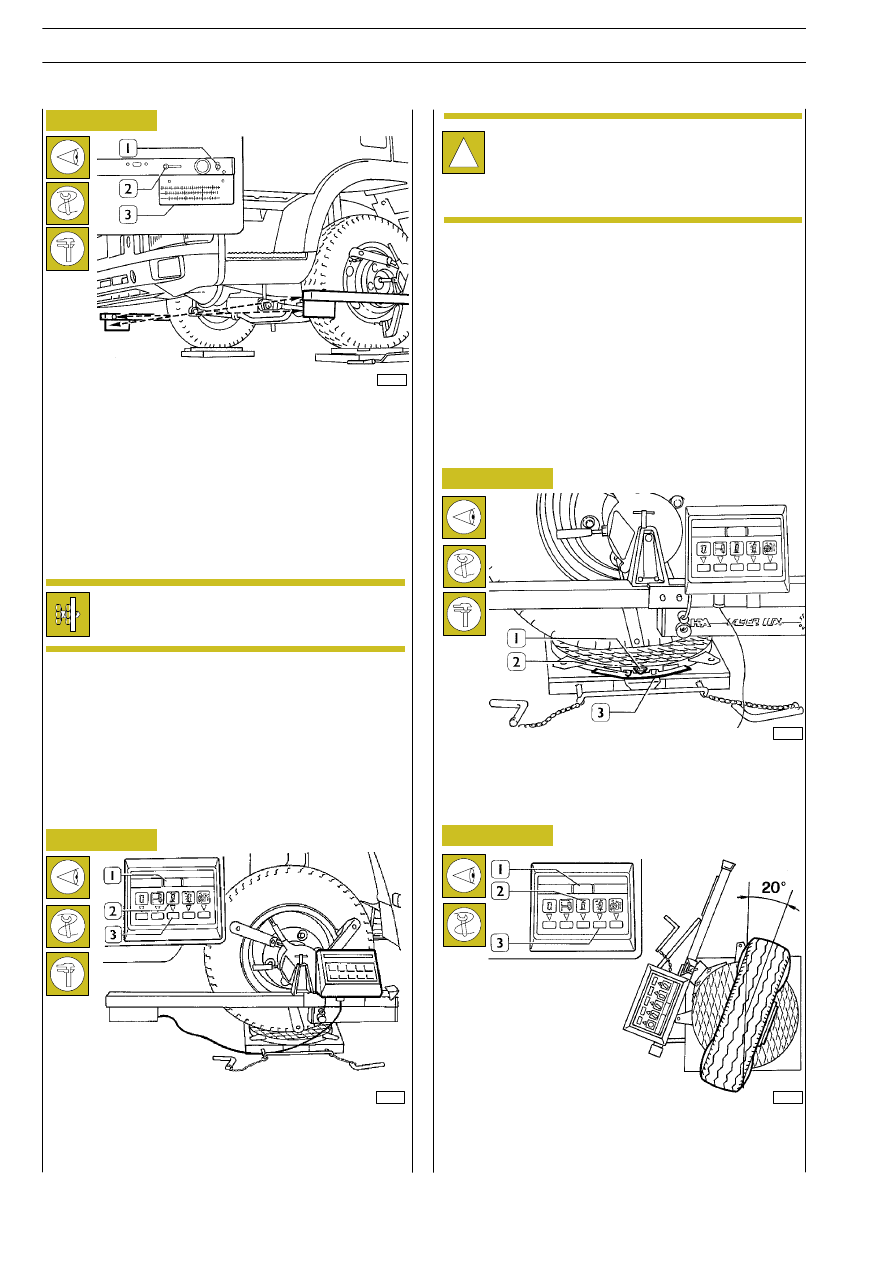
Figure 22
Figure 23
If the front wheels are aligned with the rear ones and the de-
tectors are balanced, push the wheel inclination button (3) and
the led (2) will be switched on. The digital indicator (1) will give
the value of the angle of inclination which must be 1
°.
Check upright angle of inclination (King Pin)
and clearance angle (Caster)
Check of wheel inclination (Camber)
32980
Still having detectors perfectly balanced and the wheels com-
pletely aligned, use a lever (1) to move the lens cover.
Move the lever (2) and point the light signal index to the
ruler’s graph scale (3) corresponding to the rim’s diameter.
Repeat the same operations with the opposite detector and
read the toe-in values expressed in millimetres on the graph
scales.
The algebraic sum of the two detected values must amount
to: 0.5
÷ 1.5 mm with static load.
32981
Toe-in adjustment is performed by operating on
the track rod so that toe-in for each wheel is from
0 to 0.5 mm.
Figure 24
Figure 25
!
The wheels’ angle of inclination is a fixed value which
cannot be adjusted.
Therefore, if a different value is detected, remove
and dismantle the axle, make the appropriate inves-
tigations and possible replacements.
Still having the front wheels aligned with the rear ones, loose
knurled knobs (2) and set to zero the graduated sector (3)
on the swinging plate’s index (1).
32982
Turn the wheels inwards by 20
° and push twice the upright
inclination button (3), the led (2) will be switched on and nine
horizontal lines will appear on the digital indicator (1).
32983
E
URO
C
ARGO
T
ECTOR
12-26 t
24
FRONT AXLE 5845
Base - February 2003