Iveco EuroCargo (12 to 26 t). Manual - part 116
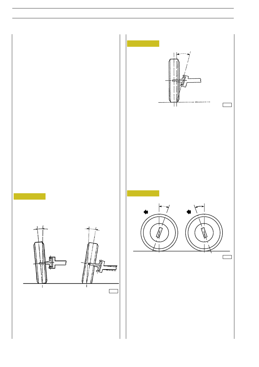
The upright angle (
β) of inclination is the one resulting from
the axis passing through the upright and the vertical to the
ground, looking at the vehicle standing before it.
When the extension of the upright axis approaches the wheel
when it is touching the ground (opposite direction compared
to the wheel’s inclination), the angle is positive. It is difficult, if
not impossible, to have a negative upright angle of inclination.
The wheel angle (
α) of inclination and the upright angle (β)
of inclination enable the wheel axis and the upright axis to get
closer to the tyre’s fulcrum on the ground as much as possible.
As a result, it is possible to reduce the tyre wear and to get
a low value of the steering torque.
In order to have a good roadholding, a low tyre wear and to
enable driving wheels to recover an upright direction after
steering, it is necessary to set the wheels according to certain
assembly angles:
- wheel angle of inclination
- upright angle of inclination
- clearance angle
- toe-in
Such angles, when correctly calculated, enable the vehicle to
maintain the right balance among the various forces involved
in its movement, in different loading conditions, which tend
to alter the wheel position on the ground.
Figure 4
Clearance angle
Wheel angle of inclination
The wheel angle (
α) of inclination is the one resulting from
the axis passing through the wheel’s centre line and the verti-
cal to the ground, looking at the vehicle standing before it.
The inclination is positive (A) when the wheel’s upper part
moves outside. It is negative (B) when the wheel’s upper part
moves inside.
32956
32957
32958
Figure 5
Figure 6
A
B
α
α
ß
The clearance angle (
γ) is the one resulting from the upright
axis and the vertical to the ground, looking at the vehicle from
one side.
If the extension of the upright axis falls beyond the wheel’s
fulcrum on the ground in the vehicle’s direction, as a rule the
clearance angle is positive (A).
It is considered negative (B) if it falls behind the wheel’s
fulcrum on the ground.
It is null if it is absolutely perpendicular to the wheel’s fulcrum
on the ground.
Such an angle enables front wheels to keep an upright position
when the vehicle is moving in an upright direction and to
recover such a position after taking a curve as soon as the
steering wheel is released by the driver.
A
B
+
_
γ
γ
Upright angle of inclination
E
URO
C
ARGO
T
ECTOR
12-26 t
8
FRONT AXLE 5845
Base - February 2003