Iveco EuroCargo (12 to 26 t). Manual - part 50
33655
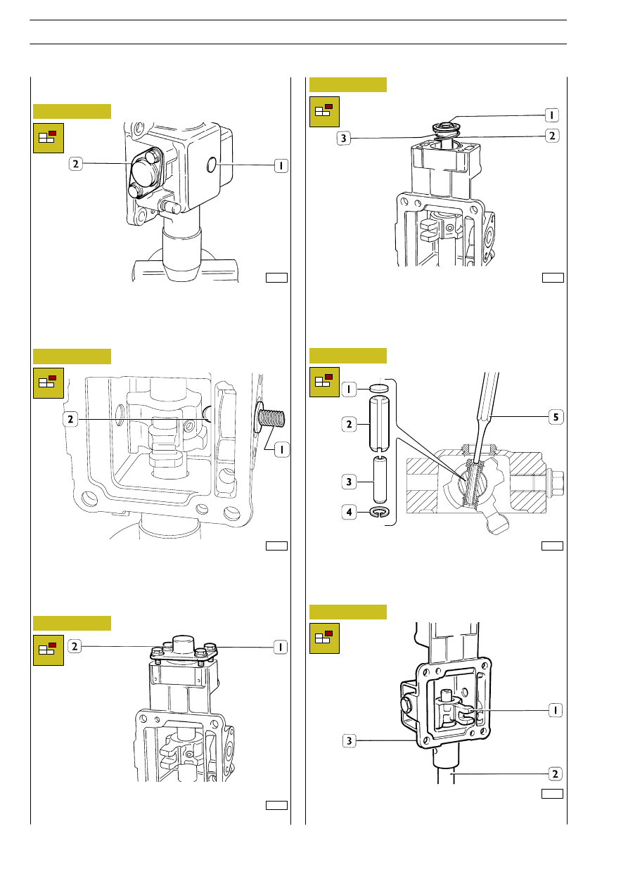
Figure 86
Tighten the shaft going out of the box in a clamp, remove plug
(1) and disassemble cover (2).
EXTERNAL CONTROL SHAFT
DISASSEMBLY
78166
Figure 87
33657
Figure 88
Unscrew screws (1) and disassemble cover (2).
Remove control box pin (2) and spring (1).
Do not mix removed elements with those of the anti-release
push rod.
2
33660
Extract, from the control shaft (2), control selector (1) and
box (3).
33658
Unscrew screw (1) and remove spacer, upper cup (3) and
spring (2). Remove lower cup.
78167
Figure 89
Figure 90
Figure 91
Remove the snap ring (4) and use a punch tool (5) having the
right diameter to push the extraction washer (1) and remove
flexible plugs (2) and (3).
E
URO
C
ARGO
T
ECTOR
12-26 t
40
GEARBOX 2855.6
Base - February 2003