Iveco EuroCargo (12 to 26 t). Manual - part 39
E
URO
C
ARGO
T
ECTOR
12-26 t
10
CLUTCH
Base - February 2003
PART
TORQUE
Nm
(kgm)
Flanged hexagonal-head screw for securing plate-pusher to flywheel
M8
23.5
± 2.5
(2.4
± 0.2)
Flanged hexagonal-head screw for securing plate-pusher to flywheel
M10
46.5
± 4.5
(4.7
± 0.4)
Hexagonal nut for securing clutch timing case to engine
M8
46
± 5
(4.6
± 0.4)
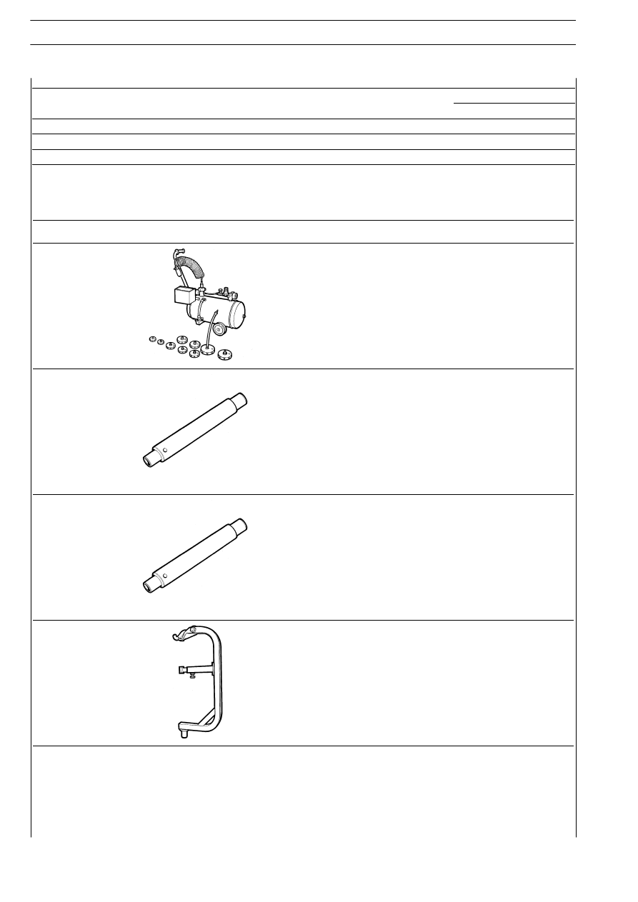
TOOLS
TOOL No.
DENOMINATION
99306010
Air drain apparatus for brakes and clutches system
99370280
Guide pin for clutch plate centring
99370306
Guide pin for clutch plate centring
99370547
Disengagement and re-engagement support for clutch assembly
(to be applied to hydraulic jack)