Iveco EuroCargo (12 to 26 t). Manual - part 20
70325
70326
18625
18882
70327
Figure 138
Figure 139
Figure 140
Figure 141
Figure 142
The rated thickness A for the cylinder head is 105
± 0.25 mm,
max. metal removal shall not exceed thickness B by 0.13 mm.
540662
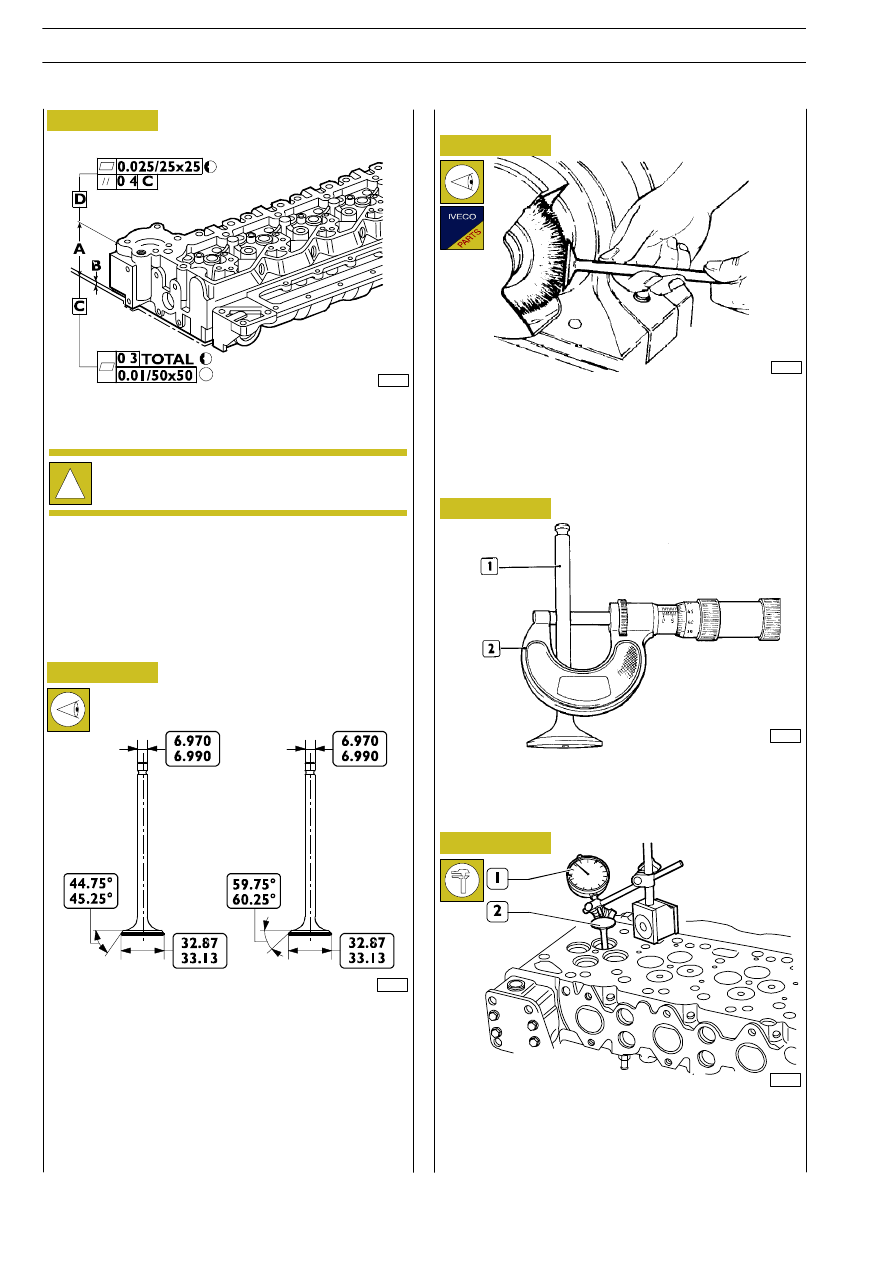
VALVES
INTAKE AND EXHAUST VALVE MAIN DATA
Remove carbon deposits from valves using the proper metal
brush.
Check that the valves show no signs of seizing, scoring or
cracking.
Regrind the valve seats, if required, using tool 99305018 and
removing as less material as possible.
Check the valve stem (1) using a micrometer (2), it shall be
6.970
± 6.999.
Use a magnetic base dial gauge (1) set as shown in the figure,
the assembling clearance shall be 0.052
± 0.092 mm.
Turn the valve (2) and check that the centering error is not
exceeding 0.03 mm.
!
After grinding, check valve sinking. Regrind the valve
seats, if required, to obtain the specified value.
Removing carbon deposits, checking and
grinding valves
Checking clearance between valve stem and
valve guide and valve centering
INTAKE
VALVE
EXHAUST
VALVE
E
URO
C
ARGO
T
ECTOR
12-26 t
70
ENGINE F4 AE 0481
Base - February 2003