Iveco Stralis AT/AD. Manual - part 286
4
INTRODUCTION
S
TRALIS
AT/AD
Base - January 2003
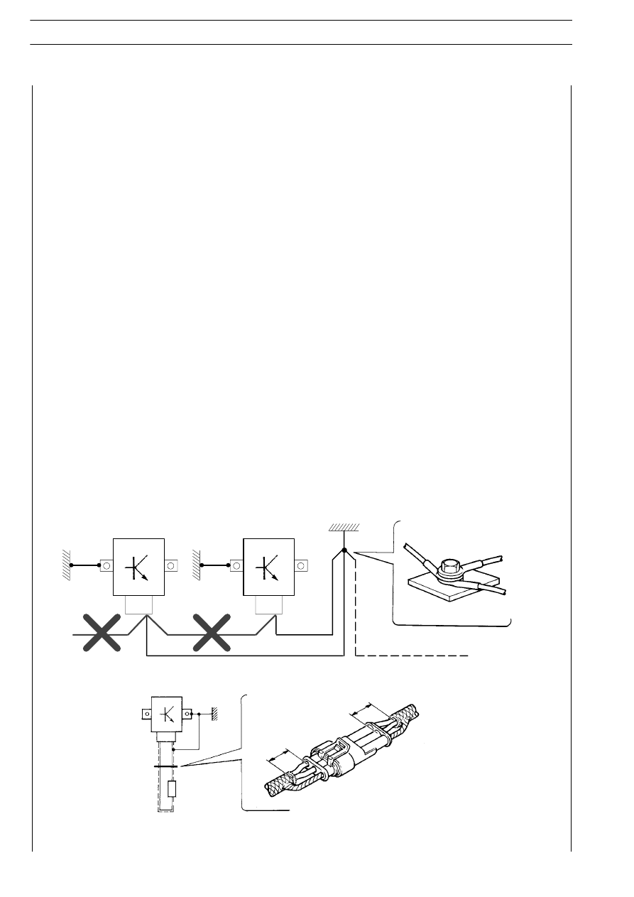
The negative leads connected to a system grounding point must be as short as possible and connected to one another
in ”star” configuration; make sure that they are tightened in an orderly and adequate manner (Fig. 1, ref. M).
Furthermore, for electronic components, the instructions to be followed very carefully are:
— ECU’s must be connected to the system ground if they are provided with a case.
— ECU negative cables must be connected both to a system grounding point, such as for instance the dash compar-
tment ground (with no ”serial” or ”chain” connections) and to the negative terminal(s) of the battery/batteries.
— Even though they are not connected to the system ground/battery negative terminals, analogue ground elements
(sensors) must have excellent insulation. As a result, special care must be devoted to the eddy resistances of
the cable terminals: oxidation, seam-folding defects, etc.
— The metal braid of shielded circuits must be in electrical contact at either end with system components.
— Only one end of the shielding braid must be connected to the system ground.
— In the presence of jointing connectors, the non-shielded portion, d, must be as short as possible in the proximity
of the connectors (Fig. 2).
— The cables must be arranged so as to run parallel to the reference plane, i.e., as close as possible to the frame/body
structure.
— Additional electromechanical systems must be connected with the greatest care to the system ground and must
not be placed alongside the cables of electronic components.
1
”STAR” CONNECTIONS OF NEGATIVE CABLES TO THE SYSTEM GROUND M
2
SHIELDING BY MEANS OF A METAL BRAID OF A CABLE LEADING TO AN ELECTRONIC COMPONENT - C. CONNECTOR -
d. DISTANCE ! 0.
C
C
d
d
-
-
M
2231
2232
2604
2603