Iveco Stralis AT/AD. Manual - part 241


  Index      Iveco     Iveco Stralis AT/AD - service repair manual 2003 year


Search            


Content   ..  239  240  241  242   ..


Iveco Stralis AT/AD. Manual - part 241


- Moreover, when crossing chassis longitudinal members or

metallic parts, check that passage holes are coated with
rubber fairlead rings and that these latter ones are in good
conditions;

- Avoid that the pipe slides along cutting edges that would

risk to create nickings;

- Having to fix the piping onto already existing ducts, take

into account the supplementary heat to which it can be
subjected (hydraulic power steering duct): in such case,
the piping must be protected with guards;

- At the end of the connection, verify that the piping,

between keying and securing, is not stretched, but must
be slightly loosened to recover higher temperature
variations, particularly for short lengths;

- Before assembling, accurately clean the pipings by blowing

compressed air in order to guarantee system operation.

- Protect the pipes in case of grinding or welding

operations on the vehicle; for such purpose, an adhesive
plate is applied in the cabin and shows the precautions to
be observed with utmost care to avoid damages.

Figure 15

Flexible pipings replacement with quick
connection fittings

For better safety and work comfortability, it is
advisable to detach the pipings during such operations.

At the end of the assembly, check the perfect seal of all gaskets
(unions, fittings, etc.).

Assembly of piping on vehicle is carried out by taking into
account some important solutions:
- Bendings must comply with minimum radiusses, in order

to avoid throttlings.

Minimum bending radius

mm

Pipings diameter

mm

13132

Make sure that pipings are not in contact with sharp
edges or with cutting metallic parts or with heat
sources, but that are distant therefrom by a minimum
safety distance of 15 mm.

6 x 1

8 x 1

10 x 1.5

12 x 1.6

16 x 2.34

approx. 40

approx. 50

approx. 60

approx. 75

approx. 100

!

!

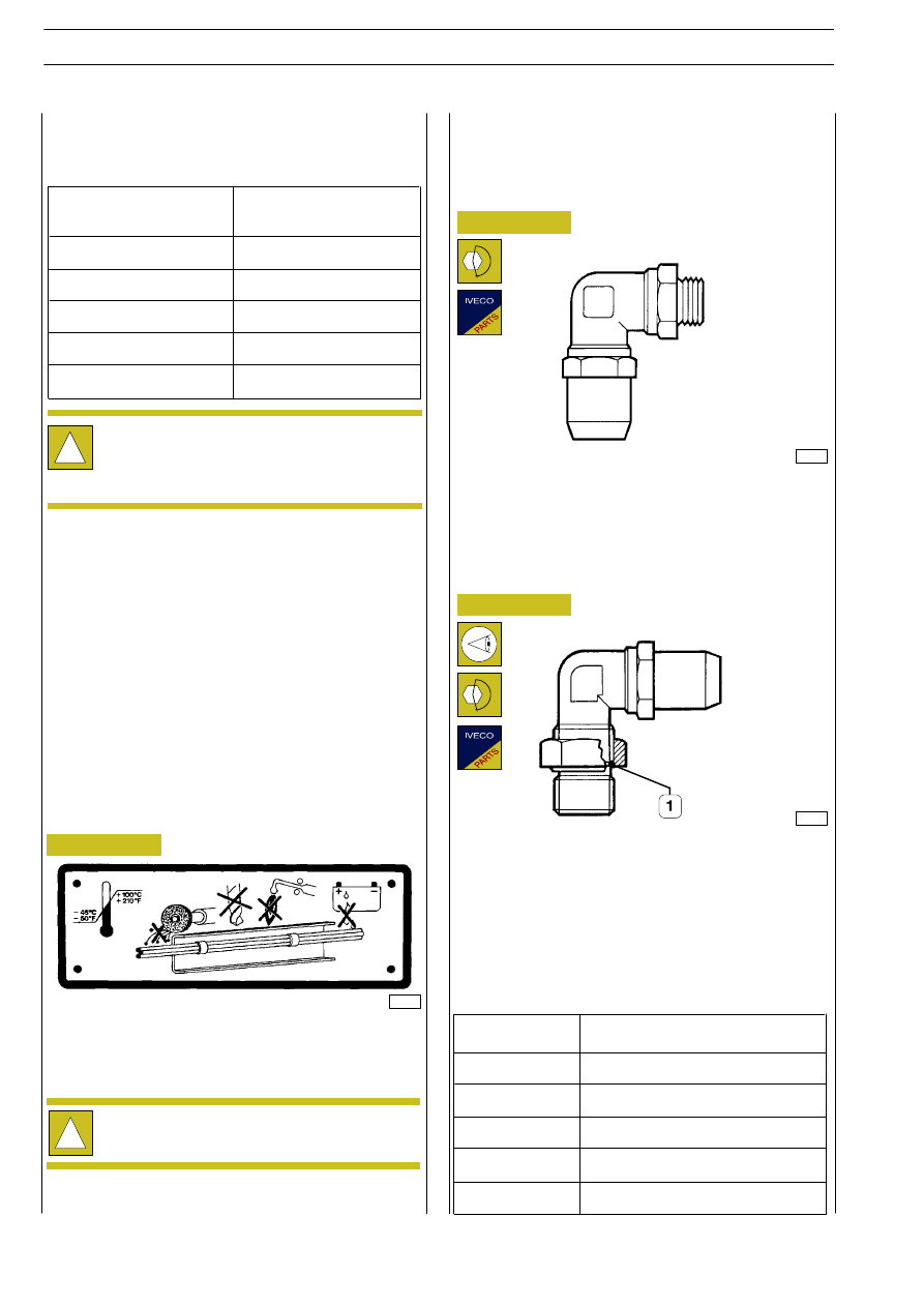
Screw the fitting in the threaded seat provided on the
pneumatic valve and lock it at the tightening torque shown in
the table.

- Check that the sealing ring (1) is into its suitable seat;
- screw the fitting till it is felt that the sealing gasket abuts

onto the valve;

- adequately swing the fitting and keeping the swingable

part still, lock the hexagonal nut at the tightening torque
mentioned in the table.

39307

Figure 16

Figure 17

39306

Rotating fittings

Swinging fittings

Rotating and swinging fittings

FITTING

TIGHTENIG TORQUE (Nm

±

10%)

THREADING

M 10 x 1.0 mm

M 12 x 1.5 mm

M 14 x 1.5 mm

M 16 x 1.5 mm

M 22 x 1.5 mm

22

24

28

35

40

S

TRALIS

AT/AD

22

AIR SYSTEM - BRAKES

Base - January 2003

- Manually insert pipe (2) into fitting (1), with a force varying

from 30 to 120 N depending on pipe diameter, so that the
notch L

1

is placed inside the fitting while the notch L

2

is

visible.

- Use homogated pipes only;
- Check the spare pipe status, on which no cracks, cuts or

nicking must be detected;

- Cut the pipe at 90

° with a max 15° error with respect to

the axis through the suitable pipe-cutting pliers 99387050
at the necessary length;

D

(mm)

In case of disassembling of fittings (1) from pneumatic
components, check the sealing ring (2) status, and if necessary
replace it.

33977

33978

6

8

12

16

Figure 18

Figure 19

Figure 20

33976

A

A = Marking to identify pipe end-of-stroke

- Strongly and indelibly mark with ink two reference

notches on both diametrically-opposed pipe faces for an
angle

≥ 75°, placed at the distances of L

1

and L

2

to

guarantee a correct assembly.

!

Dimensions L

1

and L

2

change depending on the pipe

diameter and must be measured from the longest
pipe part (see Figure 18).

19.8

20.5

25

27.1

17

18

22

24

22

23

28

30

L

(mm)

L

1

(mm)

L

2

(mm)

Figure 21

39308

FITTING

SEALING RINGS

THREADING

DIMENSIONS

Every time a piping is detached from a quick
connection fitting, it is necessary to replace the fitting
itself. Quick connection fittings are supplied complete
as spares.

M 10 x 1.0

M 12 x 1.5

M 14 x 1.5

M 16 x 1.5

M 22 x 1.5

10.1 x 1.6

11.0 x 2.0

-

15.0 x 2.0

-

Quick connection and threaded fittings, as well as
flexible pipings used with quick connection fittings
and flexible pipings used with threaded fittings, are
not interchangeable.

!

!

0

+0.5

-0.5
+1

-0.5
+1

AIR SYSTEM - BRAKES

23

S

TRALIS

AT/AD

The increase in competition in the transport sector has had the effect, among others, of constantly increasing the basic requirements
of braking systems.

The introduction of the EBS electronic brake system is the logical answer to these new needs.

It is an integrated and permanent electronic control system for the brake system of the tractor and trailer.

It supplements the ABS, ASR and EBL functions.

The system is composed of a pneumatic system and an electric system containing the following components:

Duplex control valve with electric transmitter, proportional relay valve for front axle, ABS for front axle, rear axle electro-pneumatic
modulator, trailer servo control valve.

The EBS system dialogues with the control units of the other assemblies:

Engine, Ecas, retarder and gearbox via the CAN line (VDB, Vehicle Data Bus).

EBS Benefits

Lower servicing costs.

The EBS combines many functions. The aim is to cut maintenance costs while maximizing braking safety — that is minimizing brake
lining wear.

An individual control according to the lining wear parameters on both the front and rear axles harmonizes lining wear. Distributing
the load homogeneously between all the brakes of the wheels reduces total consumption. In addition, the frequency of servicing
and changing the linings coincide. The costs of inactivity are drastically reduced.

Depending on the servicing a vehicle needs along with other factors, the owner may be able to make considerable savings. A
comparison of the maintenance costs, for the brake system, of a vehicle with EBS and one with a conventional brake system highlights
significant savings.

Tractor and trailer compatibility at any time

Harmonizing the braking processes of the entire tractor-trailer combination, especially if the combinations are frequently changed,
often with conventional means, is not satisfactory.

An inadequate balance, such as with a trailer whose braking is not sufficiently effective, will cause uneven wear of the brake linings.

The EBS will recognize all the incompatibilities between tractor and trailer, harmonizing braking automatically. When the brakes work
in the best conditions, not only are brake maintenance costs optimized, but safety and comfort are optimum too.

Complete fault-diagnosis structures

The EBS provides the owner of the vehicle with constantly updated information on the state of the brake system and the basic brakes.
This makes it possible to schedule servicing in advance. The EBS monitors all the fundamental components and functions of the brake
system.

Any defect recognized by the system is accurately highlighted. The maintenance specialist can therefore rectify the error at issue.

The high degree of safety ensured by the EBS is due to several factors:

- Lower pressure accumulation and response times for the brakes on the front, rear and trailer axles.

- Better ABS function.

- Tractor/trailer always balanced in every moment.

- Constant monitoring of the service brake system. In the event of reduced brake performance, the EBS will be able to warn the

driver.

- The integrated ASR function permits optimum vehicle stability and drive optimization.

S

TRALIS

AT/AD

24

AIR SYSTEM - BRAKES

Base - January 2003

OUT

FRONT AXLE pressure

REAR AXLE pressure

Graduated release trailer pressure

The purpose of the electronic control unit is to slow down the vehicle as quickly as possible, ensuring its stability and avoiding the
tendency for the wheels to lock.

To achieve this aim, while braking, the electronic control unit will be informed of the:

- required deceleration via the sensors inside the duplex control valve;

- pressures made available via the pressure sensors in the components;

- reaction on slowing down due to the pressures made available via the speed sensor signals.

The continuous monitoring and processing of this information, in relation to the set aim, will cause the modulating valves to activate
appropriately and optimize the braking action accordingly.

IN

Required deceleration

Braking pressure

Wheel speed

CONTROL UNIT

AIM

Slip = 0

AIR SYSTEM - BRAKES

25

S

TRALIS

AT/AD

OPERATING LOGIC


Content   ..  239  240  241  242   ..