Iveco Stralis AT/AD. Manual - part 85


  Index      Iveco     Iveco Stralis AT/AD - service repair manual 2003 year


Search            


Content   ..  83  84  85  86   ..


Iveco Stralis AT/AD. Manual - part 85


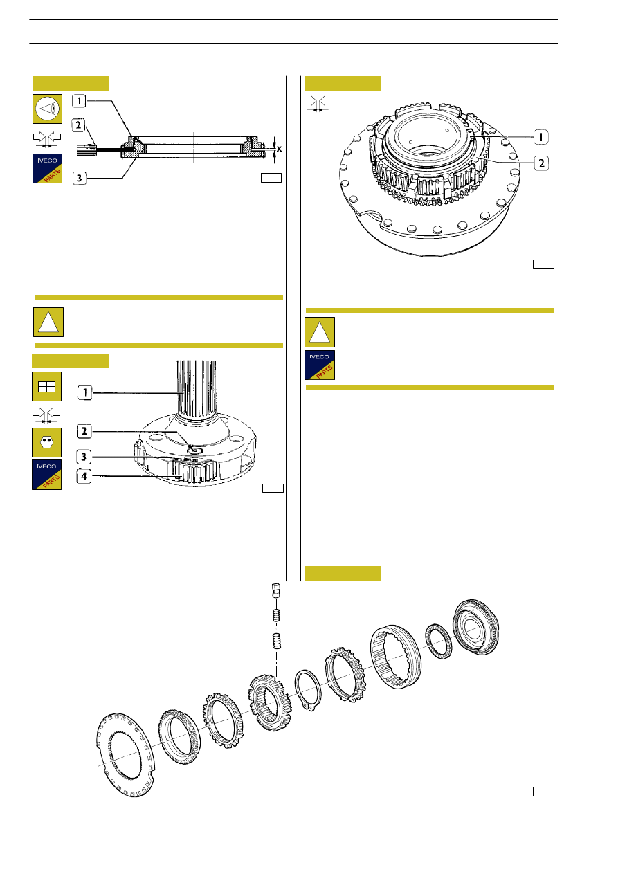
Before putting the synchronizing devices back together, check
the wear of the synchronizer rings (1) and of the coupling
bodies (3). Using a feeler gauge (2), measure the distance
between the synchronizer ring (1) and the coupling body (3)
at two opposite points. If the measured distance (X) is less
than 1.2 mm, replace the synchronizer ring (1) or the coupling
body (3).
Do not get the checked parts mixed up (it is recommended
to mark them).

71119

71410

Figure 56

Figure 57

Figure 58

Figure 59

Check the clearance between the ring (2) and its seat.

The clearance has to be between 0.0 and 0.1 mm.

COMPONENT PARTS OF THE EPICYCLIC REDUCTION GEAR UNIT SYNCHRONIZING DEVICE

13211

!

When fitting the internal rings of the bearings and
the hub for the sliding sleeve, they will first need to
be heated to approximately 100

°C for roughly 15

minutes.

19529

Check that the end float between the planet wheel holder
(1) and the planet wheels (4) is between 0.40 and 1.30 mm.
After checking the end float, fit the pins (2) of the bearings
in the planet wheel holder (1), making the reference marks
”0” punched on the pins tally with the holes (3) for the spring
pins.
Fit the spring pins in the holes (3) and notch them.

!

The circlip (1) is supplied as a spare with a different
thickness.

76

GEARBOX ZF 16 S 151 D.D. - 181 D.D./O.D. - 221 D.D.

S

TRALIS

AT/AD

Base - January 2003

Figure 60

Figure 61

Figure 62

Figure 63

Figure 64

19565

Using the keying device 99374221 (1) fit the seal in the cover
(2) of the drive output flange.

37343

Measure the depth of the bearing seat in the ERG box (1).

37344

Measure the thickness of the bearing (2).

37345

Measure the depth of the bearing seat in the cover (3)
together with the gasket (4).

37346

Determine the thickness of the adjustment ring (5) so that
between the bearing (2) and the box of the epicyclic
reduction gear (1, Figure 61) there is an end float of 0.0

÷ 0.1

mm.

GEARBOX ZF 16 S 151 D.D. - 181 D.D./O.D. - 221 D.D.

77

S

TRALIS

AT/AD

EXAMPLE

mm

-

Depth of bearing seat in box (1)

7.40+

-

Depth of bearing seat in cover (3)
together with gasket (4)

23.00=

-

Total

30.40-

-

Bedding of gasket (4)

0.0.5=

-

Total

30.35-

-

End float (0.0 - 0.1 mm), mean value

0.05=

-

Total

30.30-

-

Thickness of bearing

30.00=

-

Total

0.30

The thickness of the adjustment ring (5) has to be 0.30 mm.

Figure 65

Figure 66

Figure 67

Figure 68

To refit the rear box of the epicyclic reduction gear unit, carry
out the steps described for removal in reverse order.

The operations and assembly phases requiring specific tools,
clearance checks, adjustments or special precautions are
described below.

The tightening torques are given in the specific table.

37312

Screw the eyebolts (3) onto the rear box (2), fit the ropes
with hooks (4) and, with a movable lift, mount the rear box
on the gearbox.

Tighten the screws (1) to the required torque.

After tightening the two screws fixing the drive output flange
(2), fit the safety plate on them and notch it with tool
99370465 (1).

Take the gearbox off the stand and restore the oil level.

37359

61207

Remove the rear box of the epicyclic reduction gear unit as
described under the relevant heading.

Note down the assembly position of the switches (3) type
235N and (5) type 145N and unscrew them from the
gearbox (6).
Remove the oil vapour breather pipe (1) and the plug (2).

61177

Remove the splitter driving cylinder (3) together with the
rings (4-5).

!

There may be 3 rings on the cylinder (3).

!

The spacer ring (2) is only mounted on ZF 16 S 181
gearboxes.

Take off the ring (9). Unscrew the nut (7) and remove the
piston (8) from the rod (6).

Remove the spacer ring (2) from the main shaft (1).

Refitting the epicyclic reduction gear unit
(ERG) rear box

Removing the gearbox

78

GEARBOX ZF 16 S 151 D.D. - 181 D.D./O.D. - 221 D.D.

S

TRALIS

AT/AD

Base - January 2003

61178

Figure 69

Extract the reverse gear shaft (1).

61179

Figure 70

Remove the tube (2) from the main shaft (3).

61180

Figure 71

Unscrew the nuts (1) and take off the drive input cover (2).

61181

Figure 72

!

With some gearboxes, in order to extract the shaft
(1), it is necessary to take out the screw fixing the
plate fastening it to the gearbox.

Unscrew the screws (1) and take off the cover (2).

Take out the reverse idler gear (1) together with the roller
bearings (2 and 3).

Take off the thrust washer (4), spring (3), thrust washer (2),
adjustment ring (1) and gasket (5).

61182

Figure 73

Unscrew the nuts (1) and remove the oil pump (2).

61183

Figure 74

!

To remove the oil pump (2), do not unscrew the
screws (4). These screws secure the cover (3) to the
pump body and are unscrewed when the part has
been removed solely to overhaul the oil pump.

GEARBOX ZF 16 S 151 D.D. - 181 D.D./O.D. - 221 D.D.

79

S

TRALIS

AT/AD


Content   ..  83  84  85  86   ..