Iveco Stralis AT/AD. Manual - part 75


  Index      Iveco     Iveco Stralis AT/AD - service repair manual 2003 year


Search            


Content   ..  73  74  75  76   ..


Iveco Stralis AT/AD. Manual - part 75


31042

31043

30525

31044

31045

31046

Figure 95

Figure 96

Figure 97

Figure 98

Figure 99

Figure 100

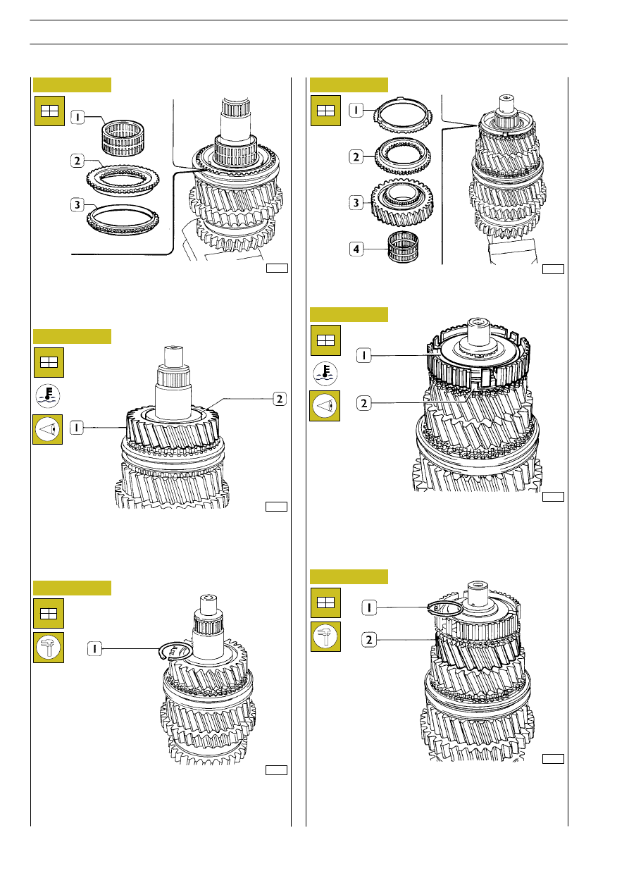
Install the synchronizer ring (3), the coupling element (2) and
the roller bearing (1).

Install the II speed gear (1). Heat the bush (2) at the tempera-
ture of 85

°C for 15’, then, install by using suitable driver.

Check that the axial backlash of the gear (1) is 0.20 to 0.45
mm.

Check that the axial backlash of the spring ring (1) in the seat
is 0 to 0.1 mm. If this is not so, select the proper thickness ring
out of those supplied spare, then install.

Install the roller bearing (4), the IV speed gear (3), the coupling
element (2) and the synchronizer ring (1).

Heat the hub (1) at the temperature of 85

°C for approx 15’,

then install it by using suitable driver. Check that the projecting
parts of the synchronizer ring (2) suitably fit the seats in the
hub (1).

Check that the axial backlash of the III speed gear (2) is 0.20
to 0.45 mm.
Check that the axial backlash of the spring ring (1) in the seat
is 0 to 0.1 mm. If this is not so, select the proper thickness ring
out of those supplied spare, then install.

36

GEARBOX ZF 9 S 109 D.D.

S

TRALIS

AT/AD

Base - January 2003

31047

30529

30788

31048

37672

37627

Figure 101

Figure 102

Figure 103

Figure 104

Figure 105

Figure 106

Fit the springs (3), the pins (4), the small blocks (5) in the rel-
evant seats on the hub (1). Compress the small blocks and in-
stall the sliding sleeve(2) that engages the III-IV speed gear.
Check that the small blocks suitably fit in place under the
sleeve.

Heat the taper roller bearing (1) at the temperature of 85

°C

for approx 15’, then install it by using suitable driver.

Heat the taper roller bearing (1) at the temperature of 85

°C

for approx 15’, then install it by using suitable driver.

Fit the spring (1) in the gearbox. Install the plate (3) and the
lever (4) and engage the end part of the lever to the spring (1)
Secure the parts to the gearbox through the spring ring (2).

Heat the seats of the cups of the taper roller bearings (1) for
the main shaft (2) and transmission shaft in the gearbox, then,
fit the components in place.

Apply tool 99370449 (1) to the main shaft (2) and engage to
the hoister.
Set the fork (3) on the shaft (2) and let the shaft in the gearbox.

ASSEMBLING THE INPUT SHAFT

GEARBOX ZF 9 S 109 D.D.

37

S

TRALIS

AT/AD

ASSEMBLING THE GEARBOX

37626

37673

37674

37675

Figure 107

Figure 108

Figure 109

Figure 110

Screw the eyebolt 99360502 (1) to the transmission shaft (2).
Engage the eyebolt to a hoister and shift the main shaft (3)
sideways to let the transmission shaft in the gearbox.

Set the gearbox to horizontal position.
Use the screwdriver to suitably set the lever (1) so as to enable
introducing the rod (5), then, connect the rod to the Reverse
speed/pickup speed gear engaging fork. Secure the fork to the
gearbox through the knuckle screws.
Install the fork (3) and sliding shoes (4) on the sliding sleeve
that engagesI-II speeds.
Position the lever (1) and fit in place the rod (5) on the sliding
sleeve that engages 1-11 speed.
Position the lever (1) and fit in place the rod (2) by engaging
it to the fork (3). Secure the fork (3) to the gearbox through
the knuckle screws.

Set the fork (2) and sliding shoes (4) on the sliding sleeve (3)
that engages III-IV speed engagement sliding sleeve (3).
Position the lever (1, Figure 108) and fit the rod (1) in place
by engaging it to the fork (2). Secure the fork to the gearbox
through the knuckle screws.
Engage 3rd speed.
Then, install the bearing plate (5) and the retaining plate (6)
and disengage 3rd speed.

Fit in place the coupling element (1) and the synchronizer ring
(3).
Open the transmission shaft (4) and the main shaft (2), then,
fit the input shaft (5) to the main shaft.
Install the oil filter (6).

38

GEARBOX ZF 9 S 109 D.D.

S

TRALIS

AT/AD

Base - January 2003

37676

37678

37677

37679

37680

Figure 111

Figure 112

Figure 113

Figure 114

Figure 115

Heat the bearing seats in the front cover (1) and fit in place
the bearing rings (2 and 3).

Fit the gasket (3) on the gearbox. Let the pipe (1) in the cover
(2) and install on the gearbox.

Set the gasket (4) on the front cover (2).
Fit in place the outer ring (3) so as to make it rest on the bear-
ing rollers free from backlash.

Rest the feeler gauge (1) on the gasket (4) and find the gap
between the outer ring (3) and the gasket (4): value A.

Use the feeler gauge (1) to find the gap between the oil pump
(2) shouldering and the coupling plane (3) of the pump to the
front cover: value B.
Thickness S of the adjusting ring is given by:

S = (A - B) + C

where: A and B are the values found out, C = 0.18 to 0.30 mm,
the prescribed pre-load.

Fit in place the adjusting ring (2) featuring the thickness value
found out during previous measuring and install the oil pump
(1). Check that the engagement opening (

→) coincide with

that on the transmission shaft (3).

ADJUSTING THE TRANSMISSION SHAFT
BEARINGS

GEARBOX ZF 9 S 109 D.D.

39

S

TRALIS

AT/AD


Content   ..  73  74  75  76   ..