Iveco Stralis AT/AD. Manual - part 24


  Index      Iveco     Iveco Stralis AT/AD - service repair manual 2003 year


Search            


Content   ..  22  23  24  25   ..


Iveco Stralis AT/AD. Manual - part 24


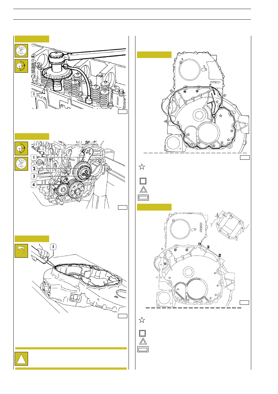
Engines without power take-off

Tighten the screws shown in the figure by means of a
dynamometric wrench, in compliance with the following order
and tightening torque:

no. 1 screw M10 x 1.5 x 100 tightening torque 42 Nm

no. 13 screws M12 x 1.75 x 80 tightening torque 63 Nm

no. 1 screw M10 x 1.5 x 180 tightening torque 42 Nm

no. 3 screws M10 x 1.5 x 35 tightening torque 42 Nm

Figure 157

Figure 158

Figure 159

45268

- Angle closing by means of tool 99395216 (1):

3

rd

phase: 90

° angle

4

th

phase: 75

° angle

Fit the oil pump (4), intermediate gears (2) with rod (1) and
tighten screws (3) in two phases:
preliminary tightening

30 Nm

angle closing

90

°

Apply sealant LOCTITE 5699 to the gear box using the
proper equipment (1).

The sealer string (1) diameter is to be 1,5

±

47592

47597

α

α

47598

Figure 160

!

Install the gear box within 10’ of the application of
the sealant.

no. 2 screws M18 x 1.25 x 125 tightening torque
24 Nm

:

Engines with power take-off

no. 1 screw M10 x 1.5 x 170 tightening torque 42 Nm

no. 10 screws M12 x 1.75 x 80 tightening torque 63 Nm

no. 1 screw M10 x 1.5 x 180 tightening torque 42 Nm

no. 3 screws M10 x 1.5 x 35 tightening torque 42 Nm

84390

no. 2 screws M12 x 1.75 x 125 tightening torque 63
Nm

¬

d

no. 8 screw M10 x 1,5 x 120

no. 2 screw M10 x 1,5 x 120 (apply to the thread
LOCTITE 275)

Figure 161

0.5
0.2

82

ENGINE F2B

S

TRALIS

AT/AD

Base - January 2003

ENGINE F2B

83

S

TRALIS

AT/AD

Second phase: closing to angle of 60

° with tool 99395216 (1).

49036

α

Figure 162

Figure 163

The crankshaft has a locating peg that has to couple
with the relevant seat on the engine flywheel.

49037

Figure 164

Position the flywheel (1) on the crankshaft, lubricate the
thread of the screws (2) with engine oil and screw them
down. Lock rotation with tool 99360351 (3). Lock the
screws (2) in three phases.
First phase: pre-tightening with torque wrench (4) to a
torque of 100 Nm (10 kgm).

α

!

If the teeth of the ring gear mounted on the engine
flywheel, for starting the engine, are very damaged,
replace the ring gear. It must be fitted after heating
the ring gear to a temperature of approx. 200

°C.

!

Fitting engine flywheel

Fit the sealing gasket (1), install the fitting tool 99346246 (2)
and drive the sealing gasket by screwing the nut (3).

45258

540850

ENGINE FLYWHEEL

60668

DETAIL OF PUNCH MARKS ON ENGINE FLYWHEEL FOR PISTON POSITIONS

A. Hole on flywheel with one reference mark, corresponding to the TDC of pistons 3-4. - B. Hole on flywheel with one reference
mark, corresponding to the TDC of pistons 1-6. - C. Hole on flywheel with one reference mark, corresponding
to the TDC of pistons 2-5. - D. Hole on flywheel with two reference marks, position corresponding to 54

°.

VIEW OF HOLES:

A - B - C

VIEW OF HOLES:

D

Figure 165

Figure 166

Figure 167

Fit the camshaft (4), positioning it observing the reference
marks (

→) as shown in the figure.

Lubricate the seal (3) and fit it on the shoulder plate (2).
Mount the shoulder plate (2) with the sheet metal gasket (1)
and tighten the screws (5) to the required torque.

73843

72436

Figure 168

Figure 169

Position the crankshaft with the pistons 1 and 6 at the top
dead centre (T.D.C.).
This situation occurs when:

1. The hole with reference mark (5) of the engine flywheel

(4) can be seen through the inspection window.

2. The tool 99360612 (1), through the seat (2) of the engine

speed sensor, enters the hole (3) in the engine flywheel (4).

If this condition does not occur, turn the engine flywheel (4)
appropriately.
Remove the tool 99360612 (1).

!

Replace the idle gear bushing (1) when wear is
detected. After installing the bushing, adjust it to j
58.010

± 0.10 mm.

- Apply gauge 99395215 (1), check and record the

position of the rod (3) for the transmission gear, tighten
the screw (2) to the prescribed torque.

45376

- Remove the transmission gear (1) and tighten screws (2)

by means of proper splined wrench, to the prescribed
torque.

45269

84

ENGINE F2B

S

TRALIS

AT/AD

Base - January 2003

Figure 170

Figure 171

Position the gear (2) on the camshaft so that the 4 slots are
centred with the holes for fixing the camshaft, without fully
locking the screws (5).
Using the dial gauge with a magnetic base (1), check that the
clearance between the gears (2 and 3) is 0.073 — 0.195 mm;
if this is not so, adjust the clearance as follows:

- Loosen the screws (4) fixing the idle gear (3).

- Loosen the screw (2, Figure 168) fixing the link rod. Shift

the link rod (3, Figure 168) to obtain the required
clearance.

- Lock the screw (2, Figure 168) fixing the link rod and

screws (4, Figure 170) fixing the idle gear to the required
torque.

Figure 172

Figure 173

44908

Fit the seals (1) (2) (3) on the injectors.

!

Before refitting the rocker-arm shaft assembly, make
sure that all the adjustment screws have been fully
unscrewed.

Using tool 99360144 (3), fasten the blocks (4) to the rocker
arms (2).
Apply the tool 99360553 (1) to the rocker arm shaft (5) and
mount the shaft on the cylinder head.

73533

Fitting pump-injectors

71775

Mount:

- The injectors (2) and, using a torque wrench, lock the

bracket fixing screws to a torque of 26 Nm.

- The exhaust brake cylinders (1) and (4) and, using a

torque wrench, fix them to a torque of 19 Nm.

- The crosspieces (3) on the valve stem, all with the largest

hole on the same side.

Fitting rocker-arm shaft assembly

45270

5

ENGINE F2B

85

S

TRALIS

AT/AD


Content   ..  22  23  24  25   ..