Iveco Daily. Manual - part 440


  Index      Iveco     Iveco Daily - service repair manual 2004 year


Search            


Content   ..  438  439  440  441   ..


Iveco Daily. Manual - part 440


286

ELECTRIC/ELECTRONIC SYSTEM

D

AILY

Base - May 2004

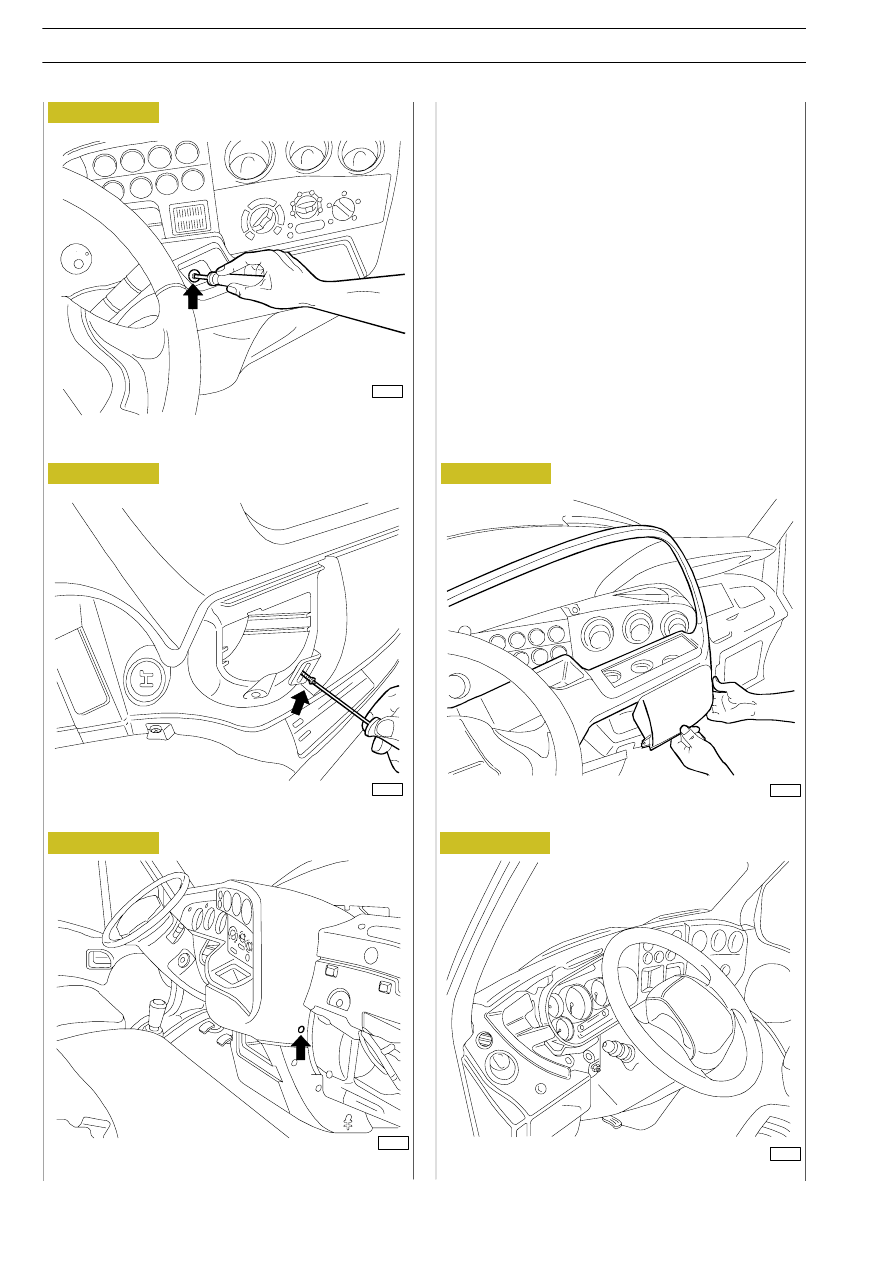
To replace the module, proceed as follows:
1. Remove  the  upper  trim  working  on  the  three  screws

shown by the arrows.

2. Lift and remove the trim taking care not to damage the

velcro stoppers.

UPPER TRIM FASTENING SCREW

UPPER TRIM FASTENING SCREW

UPPER TRIM FASTENING SCREW

TRIM REMOVAL

INSTRUMENT CLUSTER

Figure 335

8787

Figure 336

8788

8790

Figure 337

8789

8791

Figure 338

Figure 339

ELECTRIC/ELECTRONIC SYSTEM

287

D

AILY

Work on the 4 screws, 2 on either side, to remove the cluster

module with tachometer.
Disconnect the electrical connections and replace with the

module  for  tachograph  sealing  the  electrical  connections

concerning the wiring for tachograph.
Fasten the instrument cluster to the dashboard and refit the

upper and lower trim.

INSTRUMENT CLUSTER FASTENING

REMOVING THE INSTRUMENT CLUSTER

CONNECTIONS CONCERNING WIRING FOR

TACHOGRAPH

COMPLETE INSTRUMENT CLUSTER

Figure 340

8792

Figure 341

8793

8794

8795

Figure 342

Figure 343

288

ELECTRIC/ELECTRONIC SYSTEM

D

AILY

Base - May 2004

1. Replace the sensor on the gearbox with a suitable one for

tachograph.

2. Seal with lead the electrical connection to the sensor and

to the gearbox body.

If  necessary,  drill  (4  mm)  the  ribbing  on  the  gearbox (see

arrow) for passing the wire.

SENSOR REPLACEMENT ON GEARBOX

CONNECTION OF SENSOR TO WIRING

SENSOR TECHNICAL VIEW

Figure 344

8796

Figure 345

8797

Figure 346

8798

ELECTRIC/ELECTRONIC SYSTEM

289

D

AILY

Operation in bonnet

1. Disconnect the terminals of the power cables from the

battery terminals.

2. Remove the battery from the engine compartment, after

removing the fastening bracket.

3. Seal the connector between the frame and cab/bonnet

cables with sealing wire.

4. Refit the battery, re-connect the terminals to the battery

terminals,  ensuring  correct  polarity  and  calibrate  the

tachograph using the special VDO tool.

5. In the front part, seal the tachograph control unit with the

special red plug as shown.

6. Apply the labels; on the driver's door and on the tilting

plate of the tachograph control unit.

10.04.98

13 : 00

100436.8km

CONNECTOR BETWEEN CAB/BONNET AND FRAME

CABLES

FRONT VIEW OF TACHOGRAPH CONTROL UNIT

Figure 347

8799

Figure 348

8800


Content   ..  438  439  440  441   ..