Iveco Daily. Manual - part 422
214
ELECTRIC/ELECTRONIC SYSTEM
D
AILY
Base - May 2004
Through suitable control logic the control unit is able to
memorise and display a series of faults (present and/or
intermittent) that may occur to the system.
In the event of these faults the control unit still continues
controlling the system replacing the abnormal values detected
with suitable recovery" values which ensure minimal
operation of the system.
As a fault arises, the control unit shows the wording Error
Cli" on the display on the instrument cluster.
- For preliminary information it is possible to show any
faults on the display on the instrument cluster following
a precise procedure.
- For complete more thorough diagnostics it is however
necessary to use the diagnostic tools available to the
service network such as MODUS.
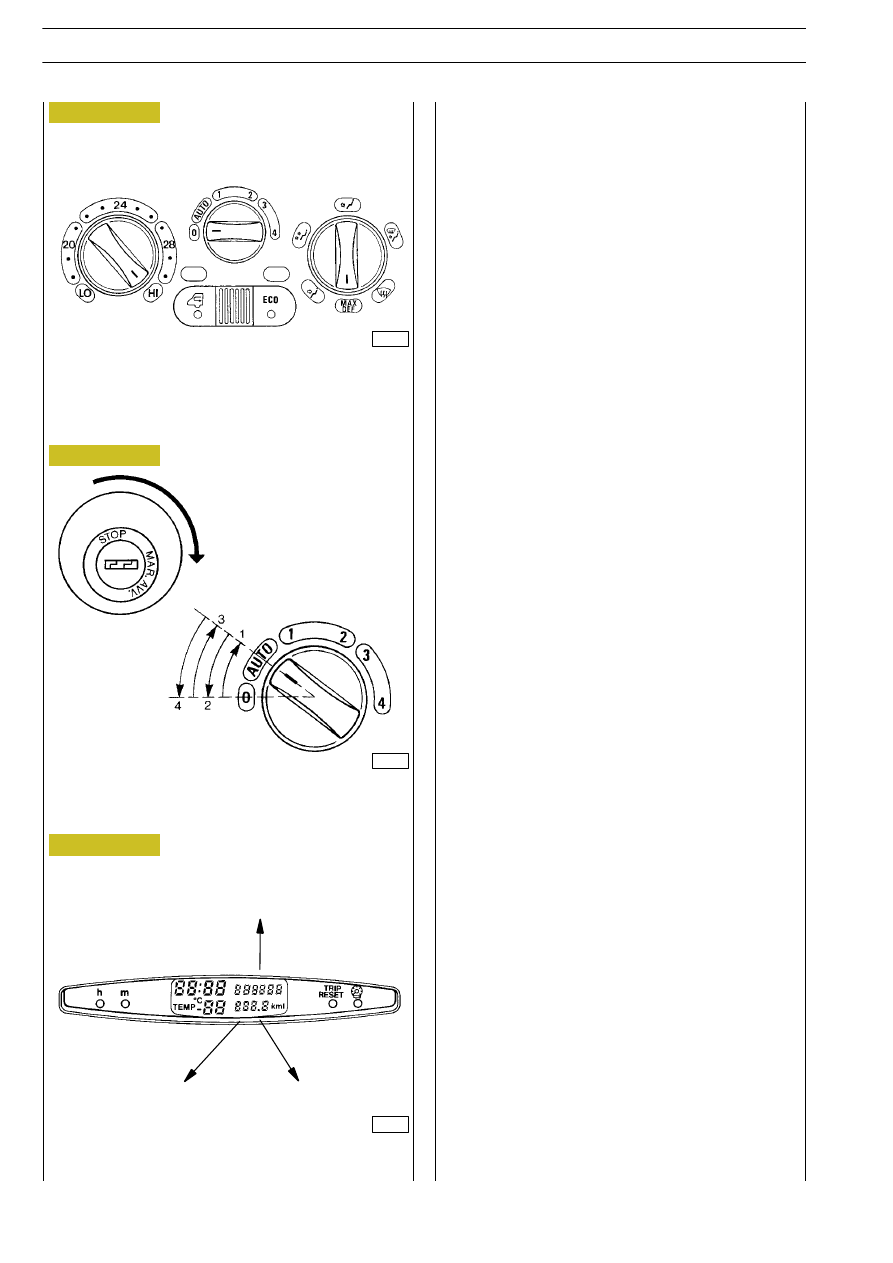
Diagnostics through blink code
To find out which is the component concerned, proceed as
follows:
Move the temperature setting knob to the HI" position (Ref.
A Figure 249).
Move the fan control knob to the 0" position (Ref. B
Figure 249).
Move the air distribution knob to the MAX DEF" position
(Ref. C Figure 249)
Engage the ignition switch (Figure 250) at the services
position (+15).
Within 10 seconds, operate the fan control knob (Figure 250)
with the following sequence:
0" ⇒ AUTO" ⇒ 0" ⇒ AUTO" ⇒ 0".
At this point the display on the instrument cluster
(Figure 251) displays the error code. If more than one error
is present, they are displayed every 3 seconds.
CLIMATE CONTROLS ASSEMBLY
A. Required temperature setting knob
B. Speed control knob
C. Air distribution knob
IGNITION SWITCH AND FAN SPEED CONTROL
KNOB SETTING
DISPLAY ON INSTRUMENT CLUSTER
Cli
⇒ 54
Error
30 / 15
A
B
C
Figure 249
Figure 250
Figure 251
000278t
000276t
000279t