Iveco Daily. Manual - part 421


  Index      Iveco     Iveco Daily - service repair manual 2004 year


Search            


Content   ..  419  420  421  422   ..


Iveco Daily. Manual - part 421


210

ELECTRIC/ELECTRONIC SYSTEM

D

AILY

Base - May 2004

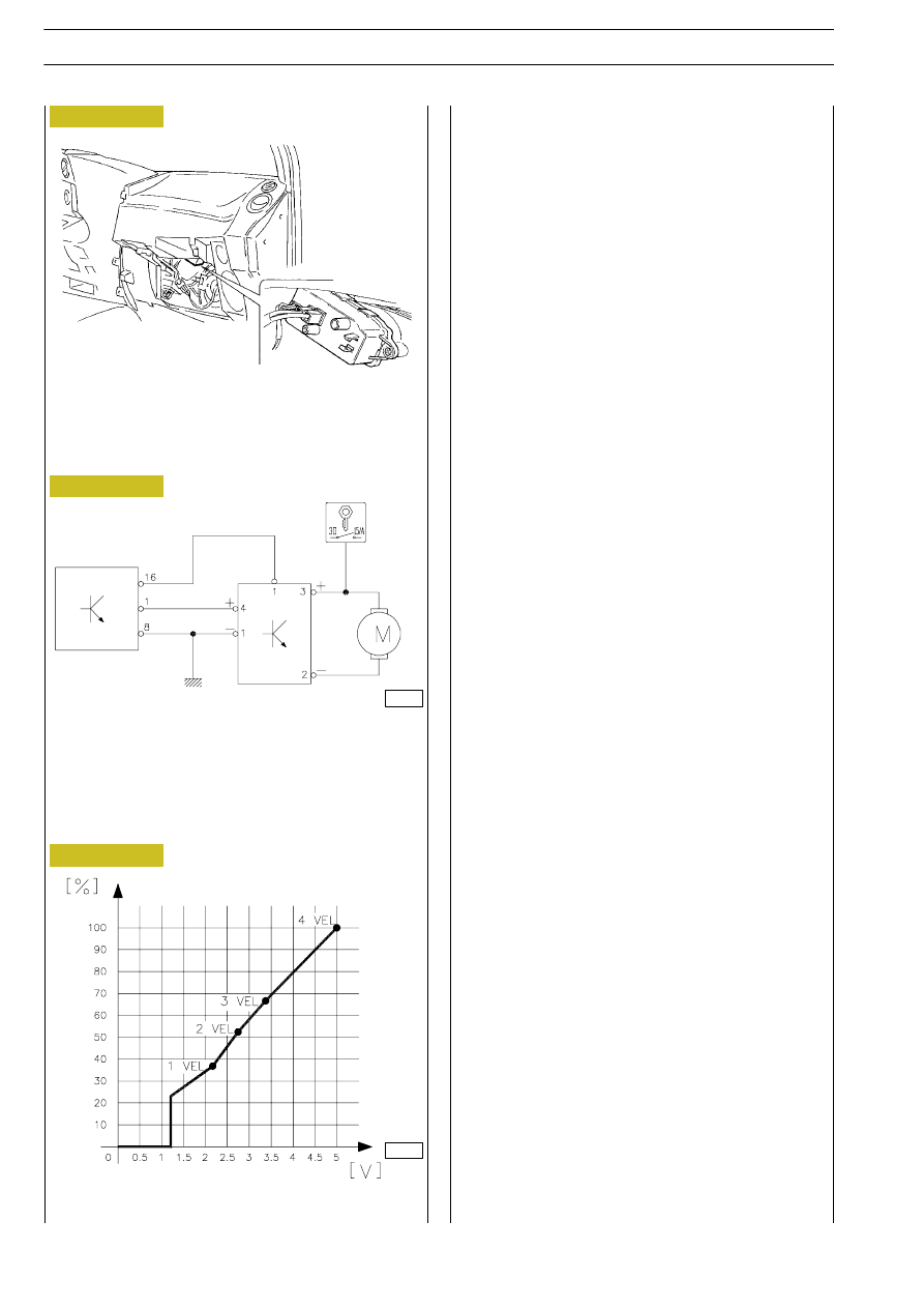
This is an electronic circuit inside the distributor unit near the

fan (Figure 241) and it adjusts the fan speed.
It is driven by the control unit with a voltage of between o and

5 Volt.
It drives the fans with a voltage of 0 to 12 Volt.
It is connected to pins 1 and 16 connector B of the control

unit.
The graph (Figure 243) represents the air flow rate in relation

to the control voltage from the control unit.

LOCATION OF FAN ELECTRONIC CONTROL

MODULE

ELECTRONIC FAN CONTROL MODULE

CONNECTIONS

A. Electronic fan control module - B. Electronic climate

control unit - C. Fan motor

GRAPH OF AIR FLOW RATE IN RELATION TO

VOLTAGE

C

B

A

Figure 241

Figure 242

Figure 243

000268t

000269t

ELECTRIC/ELECTRONIC SYSTEM

211

D

AILY

Air mixing gear motor

The gear motor formed of a motor and potentiometer is positioned inside the distributor unit and acts on the port that sends

or does not send the flow of incoming air onto the heater radiator to be able to adjust the required temperature.
The potentiometer detects the actual position of the mixing port and informs the control unit of its position. The control unit

reaches the two extreme positions, which correspond to the request for the coldest position LO" and the warmest position

HI" inverting the polarity on pins 14 and 15 of connector B of the control unit.
+ 15 / - 14 for LO" function
- 15 / + 14 for HI" function.

Motor
This is supplied by the control unit at 12 V. It is connected to the control unit on pins 14 and 15 of connector B of the control

unit. Loadless absorption is ≤ 60 mA, in D.C. it is ≤ 380 mA.

Potentiometer
It is supplied by the control unit at 5 V. The resistance is 4.7 kOhm. It is connected to the control unit on pins 7 and 9 connector

A and on pin 4 connector B of the control unit.

Pin

Cable colour

Function

1

White-Blue

Positive (5 V) for potentiometer from pin 9 connector A of the control unit

2

Grey-Black

Reference voltage (0 to 5 V) from pin 4 connector B of the control unit

3

Black

Signal earth

4

Yellow-Green Supply (0 to 12 V) for motor from pin 15 connector B of the control unit

5

-

-

6

Blue-Red

Supply (0 to 12 V) for motor from pin 14 connector B of the control unit

Figure 244

8669

212

ELECTRIC/ELECTRONIC SYSTEM

D

AILY

Base - May 2004

The gear motor is located on the front part of the distributor unit and acts on the air inlet port.
The control unit opens or closes this port to control air inlet from outside or re-circulation inverting the polarity on pins 10 and

11 of connector B of the control unit.

+ 11 / - 10 to switch on re-circulation

- 10 / + 11 for outside air inlet.
There are no intermediate positions. It is supplied by the control unit at 12 V. It is connected to the control unit on pins 10 and

11 connector B of the control unit. Loadless absorption is ≤ 60 mA, in D.C. it is ≤ 380 mA.

Pin

Cable colour

Function

1

Blue-Red

Supply (0/12 V) from pin 11 connector B of the control unit

3

Brown

Supply (0/12 V) from pin 10 connector B of the control unit

1

3

Figure 245

8668

ELECTRIC/ELECTRONIC SYSTEM

213

D

AILY

Compressor

This is fitted on the left-hand side of the engine and it is a

NIPPONDENSO SCROLL 08.
The fluid used is Freon R 134A".

The quantity of fluid is 720 grams.

The type of oil used is solely ND Oil 08.

The quantity of oil is 80 grams.

Safety pressure switches

These are fitted directly on the dryer filter (Figure 248).

The minimum A" and maximum B" pressure switches make

it  possible  to  keep  the  pressure  constant  in  the  system

between a minimum of 2 bar and a maximum of 27 bar, while

the average set at 19 bar is used to switch on the condenser

fan.

PRESSURE SWITCH UNIT WIRING DIAGRAM

A. Mnimum = 2 bar - B. Maximum = 27 bar -

C. Average = 19 bar

PRESSURE SWITCH UNIT ON DRYER FILTER

1

2

3

4

A

B

C

Figure 246

Figure 247

Figure 248

000274t

8666

8666a

COMPRESSOR


Content   ..  419  420  421  422   ..