Iveco Daily. Manual - part 395
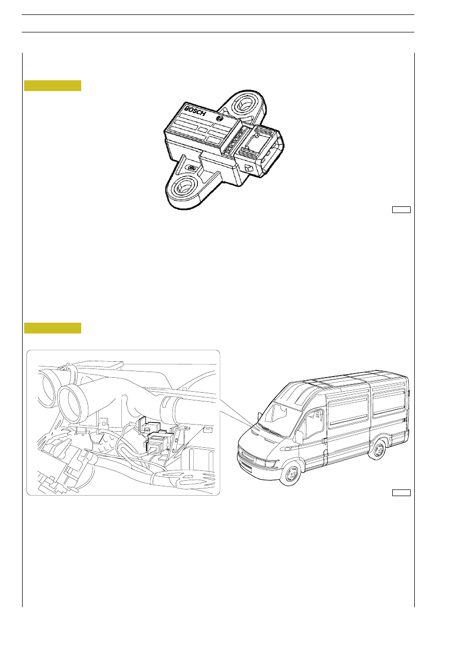
Longitudinal acceleration sensor
102116
It measures the vehicle’s acceleration and deceleration changes.
These signals continuously inform the control unit about the vehicle’s behaviour.
The comparison between these signals and those from the driver (steering-wheel position, wheel spin number/speed and pressure
on the brake pedal/accelerator position) allows the ESP control unit to define the actions to be taken. The hydraulic unit controls
brake pressure as quickly as possible, separately for every single wheel.
Moreover, the ESP system may decrease the engine revs number by means of the engine control feature.
Longitudinal acceleration sensor calibration
Figure 131/10
Figure 131/11
102111
In a horizontal position, you will obtain the sensor “zero” condition through the diagnosis instrument, i.e. you will assign its absolute
zero position.
Use a diagnosis instrument to clear the errors.
Carry out a road test, to make the control unit verify whether errors are still found. The vehicle is to be taken to a slight slope
and checked if it is kept braked for 2.5 seconds.
Drive back to the service centre, then use a diagnosis instrument to verify that the anomaly is no longer found.
132/12
ELECTRIC/ELECTRONIC SYSTEM
D
AILY
Revi - February 2005