Iveco Daily. Manual - part 393


  Index      Iveco     Iveco Daily - service repair manual 2004 year


Search            


Content   ..  391  392  393  394   ..


Iveco Daily. Manual - part 393


Four parallel channel system (II)

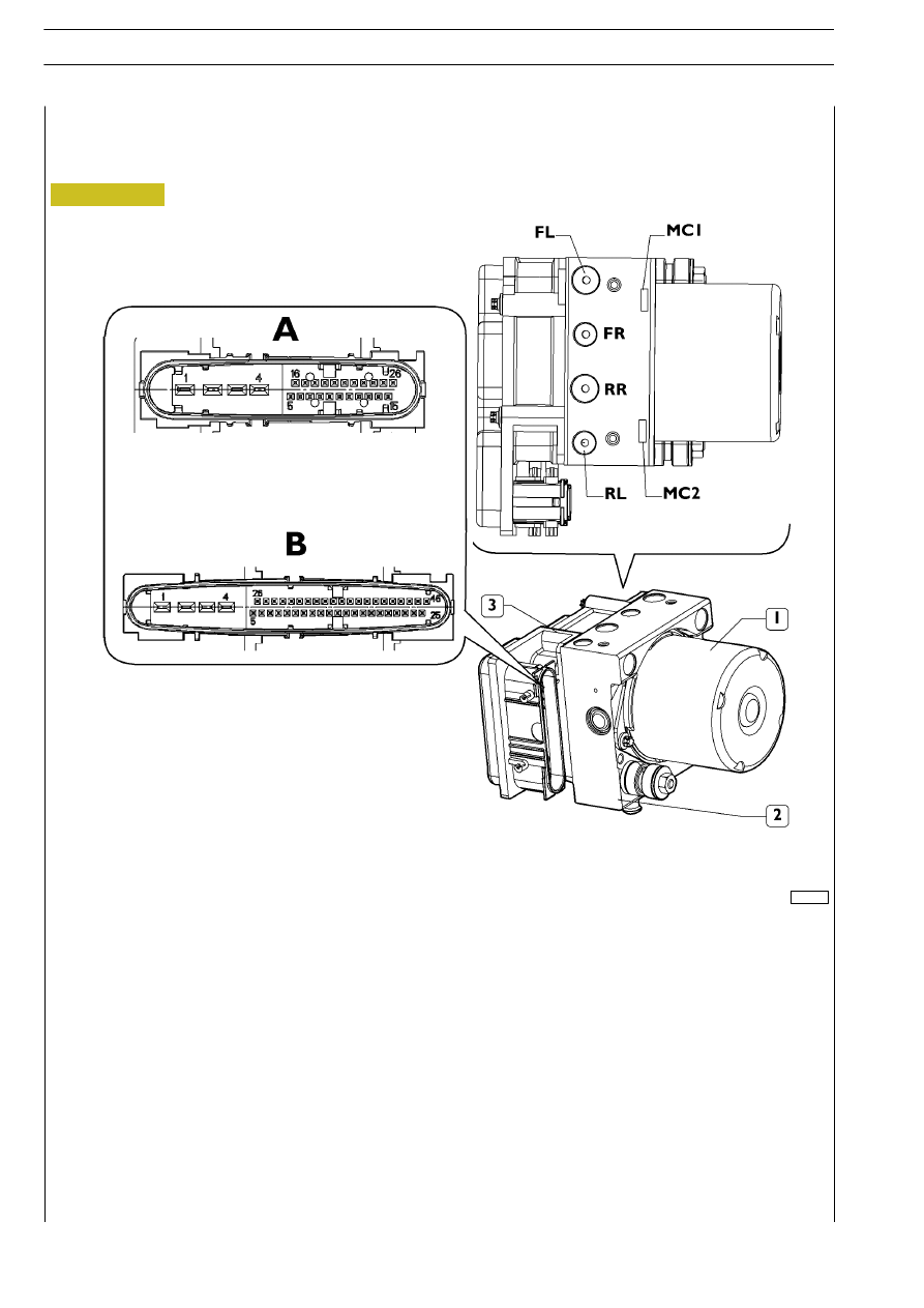
Electro-hydraulic modulator/control unit

1. Hydraulic accumulator

-- 2. Electro-hydraulic modulator -- 3. Electronic control unit -- A. ABS8 connector -- B. ESP8

connector

-- MC1. Front axle power supply -- MC2. Rear axle power supply -- LF (or FL with ABS8/ESP8 systems). Left front

axle output

-- RR. Right rear axle output -- RF (or FR with ABS8/ESP8 systems). Right front axle output -- LR (or RL with

ABS8/ESP8 systems). Left rear axle output

102114

Figure 131/2

132/4

ELECTRIC/ELECTRONIC SYSTEM

D

AILY

Revi - February 2005

ABS 8 control unit PIN OUT (X - crossed channels, II - parallel channels)

102245

Figure 131/3

ELECTRIC/ELECTRONIC SYSTEM

132/5

D

AILY

Pin (X)

Pin (II)

Function

Cable

1

1

Earth (pump control motor)

0000

2

2

Positive after fuse (pump control motor power supply enable relay)

7772

3

3

Positive after fuse (valve lock power supply enable relay)

7772

4

4

Signal earth

0000

5

5

Front left sensor

5570

6

16

-

-

7

7

Rear left sensor

5572

8

8

Rear right sensor earth

5573

9

9

Front right sensor earth

5571

10

10

Front right sensor

5571

11

11

Diagnosis K line

2299

12

12

EBD failure warning light

6673

13

13

Decelerator deactivation with ABS system ON

0315

14

14

-

-

15

15

CAN L line

Green

16

6

Front left sensor earth

5570

17

17

Rear left sensor earth

5572

18

18

Positive after fuse for ABS (KL 15)

8847

19

19

Rear right sensor

5573

20

20

Stop signalling switch — brake lights

1173

21

21

-

-

22

22

ABS failure warning light

6670

23

23

-

-

24

24

-

-

25

25

Diagnosis L line

1199

26

26

CAN H line

White

ESP 8 control unit PIN OUT (X - crossed channels, II - parallel channels)

102246

Figure 131/4

132/6

ELECTRIC/ELECTRONIC SYSTEM

D

AILY

Revi - February 2005

Pin (II)

Function

Cable

1

1

Earth (pump control motor)

0000

2

2

Positive after fuse (pump control motor power supply enable relay)

7772

3

3

Positive after fuse (valve lock power supply enable relay)

7772

4

4

Signal earth

0000

5

5

Front left sensor

5570

6

26

-

-

7

7

Rear left sensor

5572

8

8

Rear right sensor earth

5573

9

9

Front right sensor earth

5571

10

10

Front right sensor

5571

11

11

Diagnosis K line

2299

12

12

EBD failure warning light

6673

13

13

-

-

14

14

CAN L line

Green

15

15

Yaw sensor earth

9096

16

16

Yaw sensor signal

9095

17

17

Longitudinal acceleration sensor

9099

18

18

Yaw sensor reference signal

9094

19

19

Voltage stabilization signal to the acceleration sensor

9091

20

20

Side acceleration sensor signal

9092

21

21

Side acceleration sensor signal earth

0050

22

22

Decelerator deactivation with ABS system ON

0315

23

23

-

-

24

24

Diagnosis L line

1199

25

25

-

-

26

6

Front left sensor earth

5570

27

27

Rear left sensor earth

5572

28

28

Positive after fuse for ABS (KL 15)

8847

29

29

Rear right sensor

5573

30

30

Stop signalling switch — brake lights

1173

31

31

Exhaust brake actuation enable switch (ASR/ESP passive switch)

8800

32

32

ABS failure warning light

6670

33/34

33/34

-

-

35

35

CAN H line

White

36

36

Hand brake ON signal

6662

37

37

Yaw sensor test signal

9093

38/39/40

38/39/40

-

-

41

41

Stop signalling switch

1173

42

42

-

-

43

43

Reverse gear signal

2227

44/45

44/45

-

-

46

46

Speed limiter or ASR failure warning light

6672

ESP (Electronic Stability Program) operation

The ESP function controls the vehicle’s stability and side dynamics.

The main goals of this function are as follows:

- to improve stability, especially in understeering and oversteering conditions;

- to reduce the braking distance in line change conditions and on slippery roads.

The ESP function evaluates the following driver’s requests:

-

steering-wheel position;

-

wheel revs number (speed);

-

pressure on the brake pedal or accelerator position.

The ESP control unit microprocessor recognizes the specific manoeuvre and examines the vehicle’s behaviour:

-

degree of yaw;

-

wheel revs number;

-

transverse acceleration.

The microprocessor assesses the running behaviour based on the data provided, and the ESP comes into operation by acting
on the brakes.

The hydraulic modulator controls brake pressure for every single wheel as quick as possible.

The ESP may, through engine management, reduce the number of revolutions of the engine itself, in order to withstand vehicle
deceleration.

The ESP system is always active in the background, i.e. it compares the actual vehicle ride with the driver’s desired ride 50 times
a second.

Control strategy

Sudden obstacle

102246

1) Acting on the steering-wheel suddenly: danger of understeering.

2) The ESP brakes the rear left wheel

⇒ the vehicle follows the steering command.

3) The driver countersteers: Danger of oversteering

⇒ The ESP brakes the front left wheel.

4) The vehicle recovers stability.

Figure 131/5

ELECTRIC/ELECTRONIC SYSTEM

132/7

D

AILY


Content   ..  391  392  393  394   ..