Iveco Daily. Manual - part 321
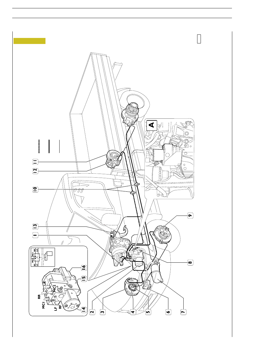
Figure 28
1.
V
acuum
b
ra
ke
-
2
.Electrohyd
ra
ulic
mod
ula
tor
-
3.
Fr
ont
b
ra
ke
d
is
k
-
4
.P
honic
w
heel
-
5
.W
heel
rev
s
se
ns
or
-
6
.V
ac
uum
d
e
vi
ce
-
7
.V
ac
uum
cha
m
b
e
r
-
8
.E
le
ctr
o
n
ic
co
n
tr
o
l
u
n
it
-
9
.Fr
o
n
t
br
ake
ca
lipe
r
-
1
0
.H
ydr
au
lic
pr
e
ssu
re
ch
e
ck
so
cke
ts
-
1
1
.R
e
ar
br
ake
di
sk
-
1
2
.R
e
ar
br
ake
ca
lipe
r
-
1
3
.Br
ake
lig
h
ts
ind
ica
tor
sw
it
ch
(on
vehicles
with
ED
C
there
ar
e
two
switches
),
inform
the
A
BS
-
E
D
C
cont
rol
unit
tha
t
the
ve
hicle
is
b
ra
ki
ng
-
14.
Hyd
ra
ulic
accumula
tor
-
1
5
.El
ec
tr
ohy
d
ra
ul
ic
modul
ator
-
1
6
.El
ec
tr
oni
c
co
ntr
o
l
uni
t.
-
A
.F
itti
ng
the
e
lect
ro
-hyd
ra
ulic
mod
ula
to
r/
cont
rol
unit
for
A
B
S
8
sy
st
ems
.
Vehicles 29L - 35S
102106
FRONT
L
H
B
RAKE
PIPING
RE
AR
RH
FRON
T
R
H
B
RAKE
PI
PI
N
G
RE
AR
L
H
E
L
E
C
TRICAL
SYSTE
M
W
IRING
Revi - February 2005
28
HYDRO-PNEUMATIC SYSTEM - BRAKES
D
AILY
Base - May 2004
Location of the main brake system components on vehicles with ABS