Iveco Daily. Manual - part 262
10
AXLE 5817
D
AILY
Base - May 2004
Axle type
5817
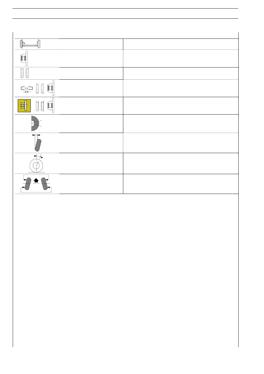
WHEEL HUBS
Wheel hubs bearings
UNIT BEARING
Hub bearings end play
-
Wheel hub bearings
play adjustment
Not Adjustable
Fixing nut torque tightening
WHEEL GEOMETRY
Wheel camber angle
(vehicle at static load)
0º
± 20’
Wheel caster angle
(vehicle at static load)
3º
± 20’
Wheel toe-in
(vehicle at static load)
2
± 1 mm