Iveco Daily. Manual - part 229
10
PROPELLER SHAFTS
D
AILY
Base - May 2004
TORQUE
PART
Nm
kgm
Ring nut for fixing to connecting shaft
250
± 25
25.4
± 2.5
Nut for screw for fixing flanges to propeller shaft
M10 x 1,5
M12 x 1.25
63.5
± 6.5
116.5
± 11.5
6.5
± 0.6
11.8
± 1.2
Nut, linkage shaft to chassis side member fixing screw
62.5
± 6.5
6.3
± 0.6
TOOLS
TOOL NO.
DESCRIPTION
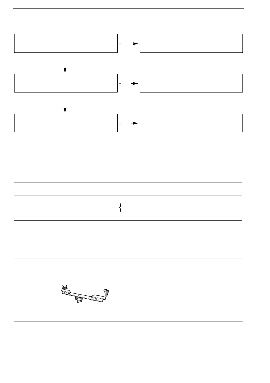
99370618
Support for removal-refitting propeller shaft
YES
NO
Elastic dowel of central support in bad condition.
Replace the support.
Central elastic support bearing in bad condition or
excessive play.
Replace the support.
Flange fixing screws or ring nuts on propeller shaft tang
loose.
Tighten the screws or the ring nuts to required driving
torque.
YES
NO
YES
TIGHTENING TORQUES