Iveco Daily. Manual - part 223


  Index      Iveco     Iveco Daily - service repair manual 2004 year


Search            


Content   ..  221  222  223  224   ..


Iveco Daily. Manual - part 223


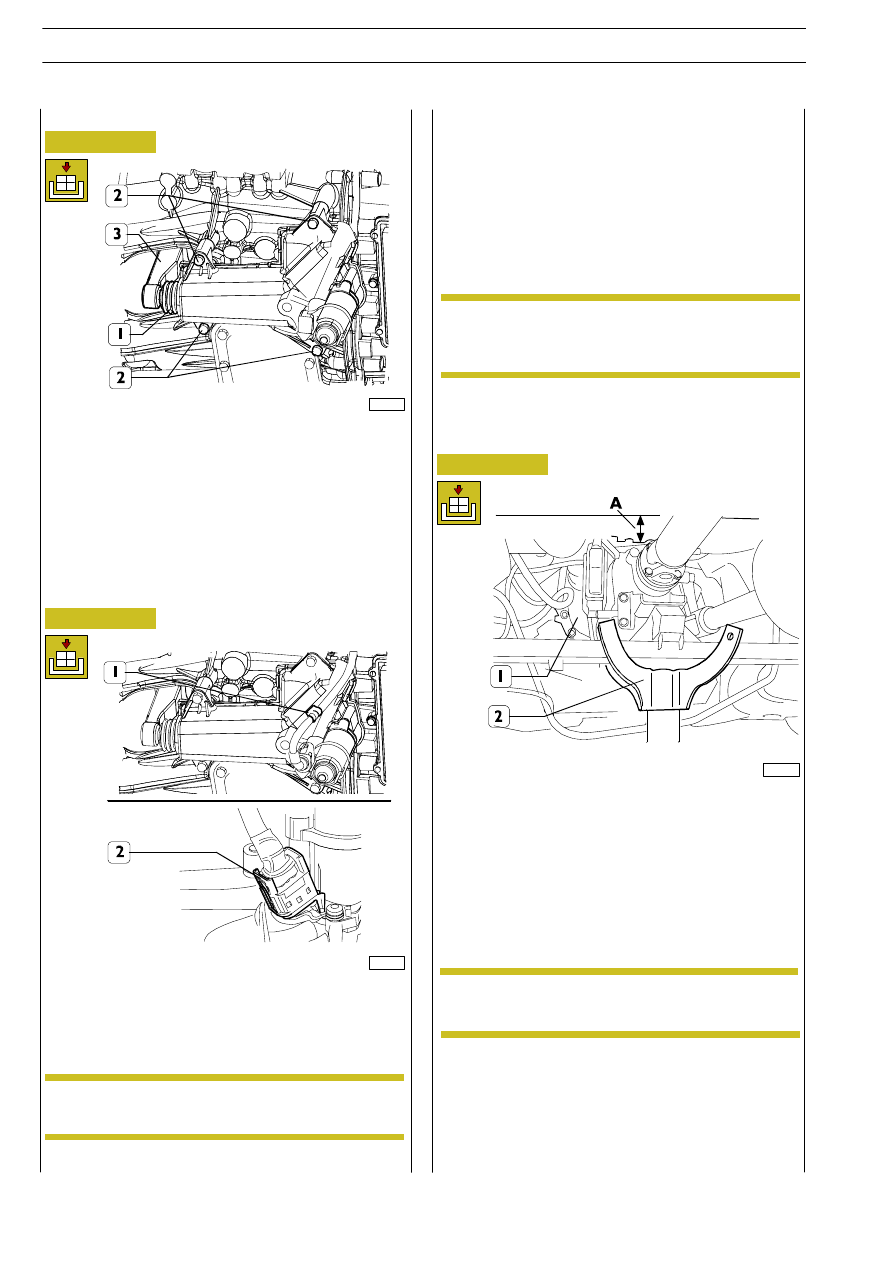
Fit connector (2) by pressing it until it gets engaged.

Secure the cable by means of strap (1).

Connect the battery cable.

Place a pit lift (2) under gearbox (1). Unscrew the gearbox
crossbar fastening screws. Lower the lift so as to obtain a
distance “A” of 12-13 cm between the actuator and the
cabin floor.

102173

102189

102190

Position clutch actuator tip (1) into fork aperture (3).

Tighten the four fastening screws (2) to the specified torque.

Refitting

Figure 131/59

Figure 131/60

Figure 131/61

500520100

GEARBOX ACTUATOR

Place the vehicle in a pit, or on an auto lift or special
supporting stands.

Disconnect the battery cable in the engine compartment.

Take off the clutch actuator, as described on page 122/25.

Removal

The actuator, positioned in the upper part of the
gearbox, cannot be accessed, owing to the very
narrow space between the cabin floor and the
actuator itself.

NOTE

Pr o c eed as it follows:

This operation must be carried out with the greatest
care, avoiding hitting the front part of the power unit.

After re-attachment has been completed, perform
the specific calibration procedure by means of the
diagnosis instrument described on page 122/31.

NOTE

NOTE

122/26

6 AS 300 VD TRANSMISSION

D

AILY

Revi - February 2005

- Apply an even coat of LOCTITE 574 sealant on the

gearbox actuator supporting surface.

- Position the actuator into its seat with the greatest care.

- Tighten the nuts or screws to the specified torque.

Open the engine hood.

Unscrew screw (1), disconnect the battery cables and take
off battery (2). Take connector (3) off EDC central unit.

102191

102192

102193

Figure 131/62

Figure 131/63

Figure 131/64

Take electric connectors (2) off the actuator.

Unscrew electric motor support fastening screw (4). Take off
supports (3).

Use a suitable tool (5) to remove the eight fastening screws
(1), then take off gearbox actuator (6).

Clean the supporting surface of the actuator on the
gearbox case.

NOTE

Refitting

Re-attachment is carried out by reversing the order of
detachment operations. Also follow the advice below:

After re-attachment has been completed, perform
the specific calibration procedure by means of the
diagnosis instrument described on page 122/31.

NOTE

769152104

CHASSIS WIRING - GEARBOX

Removal

Place the vehicle in a pit, or on an auto lift or special
supporting stands.

6 AS 300 VD TRANSMISSION

122/27

D

AILY

Remove the straps (shown by arrows) that secure the cable
to the gearbox.

102194

102196

Figure 131/65

Figure 131/67

Disconnect wiring (1) from the gearbox control unit, taking
care that it is not hit or does not get caught.

After the re-attachment operation has been
completed, verify, by getting connected to the
vehicle by means of the diagnosis instrument, that
no error is found in the gearbox control unit fault
memory.

NOTE

Refitting

Re-attachment is carried out by reversing the order of
detachment operations. Also tighten the nuts or screws to
the specified torque.

769152104

GEARBOX WIRING -
GEARBOX

Removal

Place the vehicle in a pit, or on an auto lift or special
supporting stands.

Disconnect the battery cable in the engine compartment.

102195

Figure 131/66

Take full wiring (1) off the vehicle.

122/28

6 AS 300 VD TRANSMISSION

D

AILY

Revi - February 2005

Press connector springs (2) inwards (see arrows).

Remove the connector from clutch actuator (1).

Re-attachment is carried out by reversing the order of
detachment operations. Also follow the advice below:

- Lay the wiring onto the gearbox by fitting the same with

brackets at the specified points, then place it on the engine,
taking care that it does not get pinched.

- Check for correct insertion of connectors, which can be

felt when the locking bracket has been closet.

102198

102199

102200

Figure 131/68

Figure 131/69

Figure 131/70

Remove connector (1) from control unit (2), by releasing the
pull-back spring downwards, as shown by the arrow.

Refitting

After the re-attachment operation has been
completed, verify, by getting connected to the
vehicle by means of the diagnosis instrument, that
no error is found in the gearbox control unit fault
memory.

NOTE

Remove the connectors (1) from the gearbox actuator
electric motors by pressing the fastening springs, as shown
by the arrows.

6 AS 300 VD TRANSMISSION

122/29

D

AILY


Content   ..  221  222  223  224   ..