Iveco Daily. Manual - part 215


  Index      Iveco     Iveco Daily - service repair manual 2004 year


Search            


Content   ..  213  214  215  216   ..


Iveco Daily. Manual - part 215


85961

51952

Figure 100

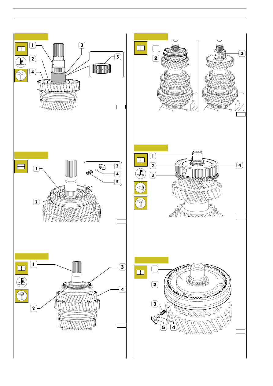
Heat the spacer ring (2) to a temperature of approx. 80

° ÷

110

°C and mount it on the main shaft (1). Check the end float

of the gear (4); this should be 0.15

÷0.3 mm.

Heat the bushing (3) to a temperature of approx. 80

° ÷ 110°C

and mount it on the main shaft (1).
Mount the roller bearing (5).

Turn the main shaft over and position the half roller bearings
(3) on it.
Mount the 6th gear (2) and position the synchronizer ring (1)
on it.

1

Fit reverse gear (1).
Fit sliding sleeve (2) on reverse gear hub (1).
Insert the springs (5), the pads (3) and the balls (4) in the hub
seats (1) and arrange them with respect to the sliding sleeve
(2).

85950

85951

Figure 101

Figure 102

Fit the synchroniser ring (2).
Heat the gear ring (3) to 110

° ÷ 150° and fit on primary shaft

(1).
Check reverse gear play (4) which must be 0.15

÷ 0.4 mm.

Heat the hub (2) to a temperature of approx. 80

° ÷ 110°C

and mount it on the main shaft (1) taking care that the projec-
tions (3) of the synchronizer ring are positioned in the seats
in the hub (2).

Mount the retaining ring (4) whose thickness produces null
end float in its seat.

51990

51991

Figure 103

Figure 104

Mount the sliding sleeve (2).

Put the springs (3), plugs (5) and balls (4) into the seats in the
hub (1) and position them under the sliding sleeve (2).

Figure 105

1

116

6 S 380 O.D. TRANSMISSION

D

AILY

Base - May 2004

During assembly, the gaskets, retaining rings, O-rings,
spring pins, safety plates and springs must always be
replaced with new parts.
The nuts and screws must be tightened to the re-
quired torque unless specified otherwise, with the
thread dry and degreased.

85952

Figure 106

Heat the bearing (2) to 80

÷110°C and fit on primary shaft (1).

Fit the circlip (4) and synchroniser ring (3).

Mounting the transmission

Adjusting the transmission shaft bearing end
float

The transmission shaft bearing end float is only ad-
justed if the bearings, transmission shaft gears, trans-
mission shaft, transmission or rear cover have been
replaced or if too much clearance has been found.

Rods - forks - selector - driver

90224

Figure 107

Spring pegs must be positioned with the cutting edge
placed level.

NOTE

NOTE

NOTE

51993

Figure 108

Determine the thickness of the ring (1) for adjusting the
transmission shaft bearing end float, proceeding as follows:

- position the thinner adjustment ring (1) 1.65 mm thick in

the seat in the transmission (3);

- heat the seat of the bearing (2) to approx. 60

°C. Mount

the external ring of the bearing (2) with the punch
99374091 and grip 99370007, see Figure 110;

- mount the transmission shaft complete with the internal

rings of the tapered roller bearings;

- mount the external ring of the rear bearing in the rear

cover in a similar manner to the front one (see
Figure 110);

- mount the rear cover on the transmission;

- screw on the 8 fixing screws so that between one screw

and another there is a hole for a free screw and tighten
them to the required torque;

- turn the transmission shaft to settle the bearings;

1. Rod with reverse gear engagement fork - 2. Main rod -

3. Rod with 1

st

-2

nd

gear engagement fork. - 4. Fork control

rod (5).- 5. 3

rd

-4

th

gear engagement fork - 6. Fork control

rod (7) - 7. 5

th

-6

th

gear engagement fork

Check the state of the plugs (2) of the 3

rd

-4

th

-5

th-

6

th

gear en-

gagement fork and replace them if they are worn.
To replace the forks of the selector and driver from their re-
spective control rods it is sufficient to remove the retaining
spring pins with a suitable punch.
For assembly, carry out these steps in reverse order, replacing
the spring pins.

Disassembly - assembly

6 S 380 O.D. TRANSMISSION

117

D

AILY

Base - May 2004

52512

Figure 109

Figure 110

- using a comparator (2) zeroed on the 5th gear toothing

of the transmission shaft (1) measure its end float A
through the opening for the power take-off connection
and note it down.

The thickness is given by:

S

C

Where:

= measured end float, e.g. 0.18 mm;

= average bearing pre-load, e.g. 0.02 mm;

= adjustment value used for the measurement 1.65 mm;

Position the adjustment ring (1, Figure 108) of the thickness
determined with the above measurement. Heat the bearing
seats of the box to a temperature of approx. 80

°C and

mount:
- the external ring (3) of the front tapered roller bearing

with punch 99374091 (2) and grip 99370007 (1);

- the ball bearing (6) with a general punch;
- the bushing with ball bearing (9) and the roller bearings

(4-5) with a general punch.

Position the retaining plates (7) and secure them to the box,
tightening the screws (8) to the required torque.

51996

S

0, 18 0, 02 1, 65 1, 85

Then mount the rear cover, transmission shaft and external
ring of the front bearing.

Heat the bearing seats of the rear cover (1) to a temperature
of approx. 80

°C and mount:

- the external ring (3) of the tapered roller bearing with

punch 99374091 (2) and grip 99370007 (1);

- the ball bearing (4) and the bushing with ball bearings (7)

with a general punch.

Position the retaining plates (6). Secure these to the rear
cover, tightening the screws (5) to the required torque.

51997

Figure 111

Clamp the primary shaft (13) in a vice, fit on it the synchronis-
ing ring and the input shaft (8).
Fit tool 99360522 (10) on the input transmission shaft (8) and
fasten with the circlip (9).
Couple the secondary shaft (2) to the primary shaft (13) and
fasten by tightening the screw (1) on the tool (10).
Fit the clutch forks: 3

rd

— 4

th

speed (4) and 5

th

— 6

th

speed (3)

on the relevant sliding sleeves.
Couple the rods (11 and 13), fit the relevant forks on the slid-
ing sleeves and clamp the rods with the sleeves of tool
99360522 (10).
Couple the reverse gear (7) with the shafts (2 and 13) and
fasten it to them with the part of the bracket (5) tighten the
screw (6).

90225

Figure 112

118

6 S 380 O.D. TRANSMISSION

D

AILY

Base - May 2004

90226

Figure 113

Figure 114

Place the roller bearings (2) in the reverse gear (1).

Fit the stem (2) and the support (3) so that the respective
holes for the fastening screw are aligned with the relevant hole
on the rear cover (5).
Drive in the fastening screw (6) of the stem (3) and the
support (4) on the rear cover (5) and tighten it to the
prescribed torque.

Fit the rod (3) in the rear cover (4).

Hook hoist to tool 99360522 (1), lift the unit (2) as previously
mounted, and partially insert it into the rear cover (4).

During this operation, check that the output shaft goes into the
supporting ball bearing and the control rods (5 -6) go into their
respective seats.

Screw tool 99370234 pin (7) into output shaft hole (2) and
fit bushing (4) and spacer (5) on tool.

Screw on the nut (6) and at the same time lower the hoist so
the output shaft (2) is positioned on the rear ball bearing (3).

Remove tools 99360522 (1) and 99370234 (4-5-6-7).

52000

Figure 115

Figure 116

Fit the control rod (1) of the 3

rd

— 4

th

speed and the main rod

(2) in the rear cover (3).

90227

eft

90210

6 S 380 O.D. TRANSMISSION

119

D

AILY

Base - May 2004


Content   ..  213  214  215  216   ..