Iveco Daily. Manual - part 185
Revi - February 2005
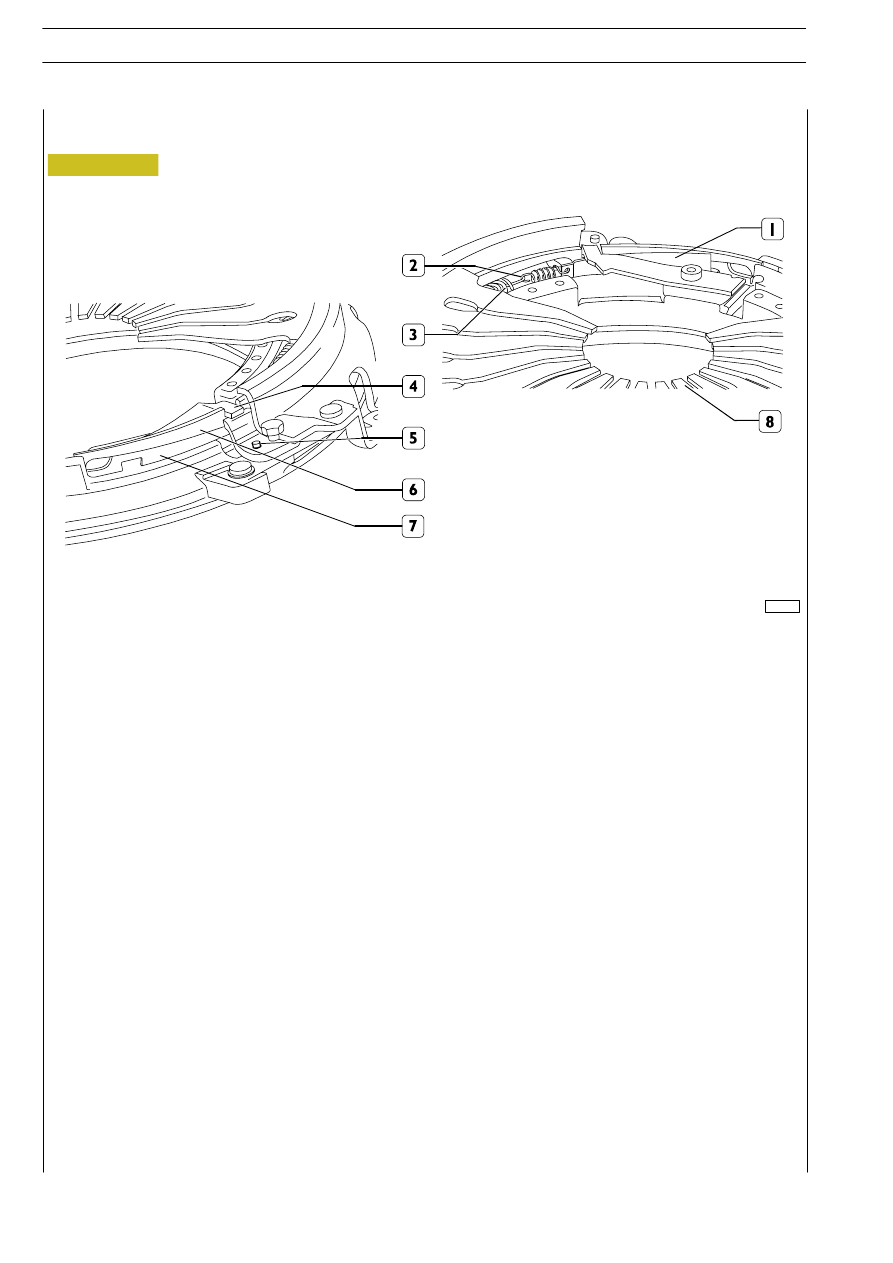
1. Sliding wedge - 2. Wedge (1) actuating spring - 3. Wear recovery ring (6 & 7) actuating spring - 4. Wear indicator - 5.
Retainer - 6. Wear recovery upper sliding ring - 7. Wear recovery lower ring - 8. Diaphragm spring
102089
Figure 19
Description
The automatic wear recovery device is placed between the diaphragm spring and the thrust plate of the pressure plate assembly.
It is essentially made up of wedge-shaped rings which recover, under sliding conditions, the clutch disc wear real-time, while keeping
both the diaphragm spring characteristics and the force required to actuate the spring unchanged.
CLUTCH WITH AUTOMATIC WEAR RECOVERY - COMBINED WITH 6 AS’300 VD GEARBOX
Operation
Automatic wear recovery takes place in two separate phases:
- Phase 1: every time the clutch is closed (engaged) and the clutch disc wear — as detected by retainer (3) — is such that the
pressure plate is made to travel an extra stroke, spring (4) will disengage wedge (1), which will be pulled by spring (2) and will
stop again against spring (4) and retainer (5) after travelling a stroke equal to the disc wear.
- Phase 2: when the clutch is opened (disengaged), diaphragm spring (8) will release wear recovery rings (6 & 7); as a result, spring
(3) will, by causing lower ring (6) to slide over upper ring (7) due to the inclined planes of the same, lift the latter by an amount
equal to the clutch disc wear.
CLUTCH
D
AILY
24
Base - May 2004