Iveco Daily. Manual - part 145


  Index      Iveco     Iveco Daily - service repair manual 2004 year


Search            


Content   ..  143  144  145  146   ..


Iveco Daily. Manual - part 145


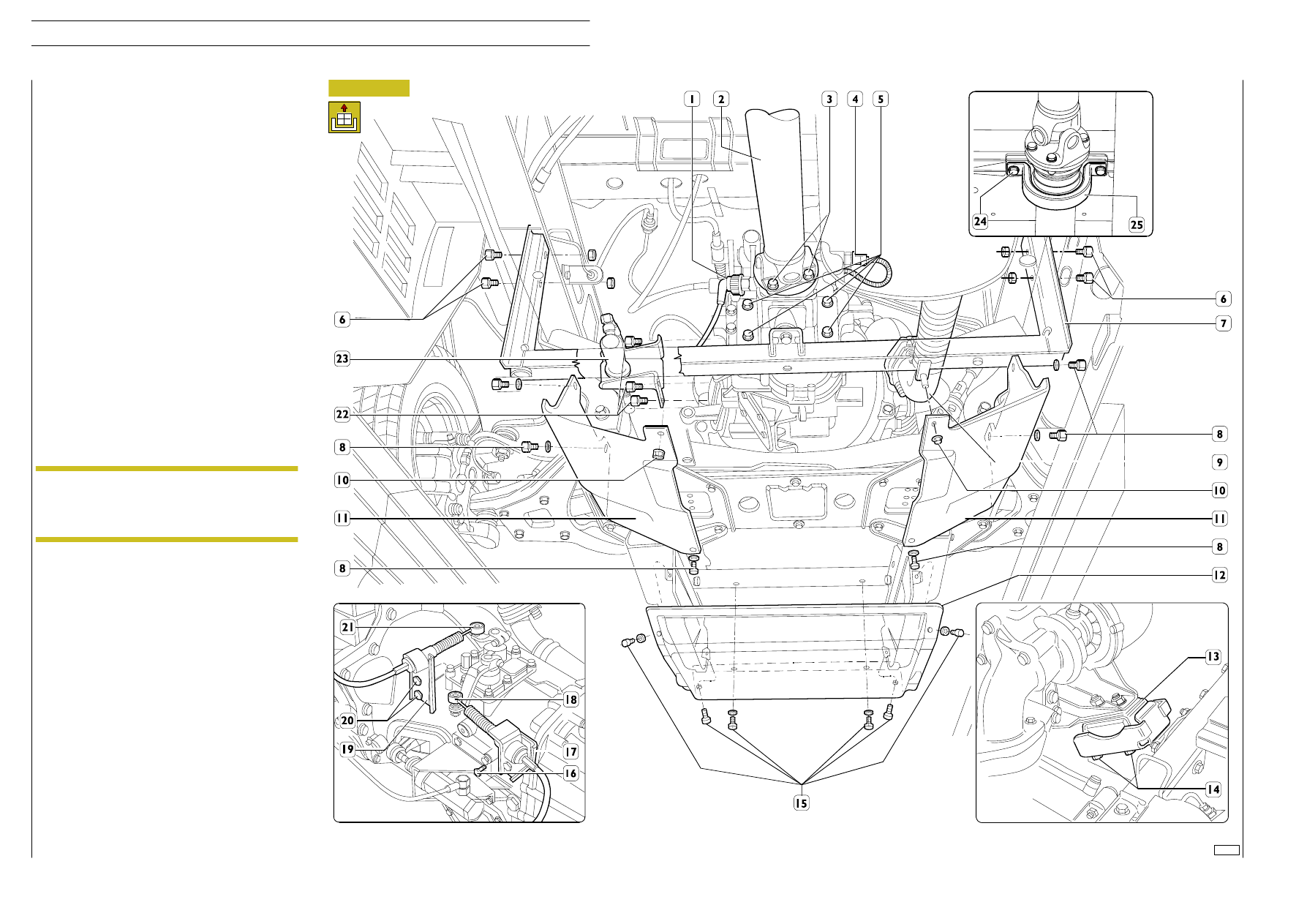
- Disconnect the screws (16 and 20) securing the brackets

(17 and 19) and disconnect the ”bowdens” (18 and 21)
from the gearbox.

- Unscrew the fixing screws (22), move the clutch control

cylinder (23), with its bracket, and fasten it to the chassis
frame appropriately.

- Remove the sealing from the ring nut (1), unscrew it and

disconnect the speedometer control cable.

- Disconnect the electrical connection (4) from the

reversing light switch.

- Disconnect the exhaust pipe (9) from the turbocharger

outlet pipe.

- Put a jack under the gearbox to support it.

- Disconnect the bracket supporting the gearbox on the

rear crosspiece by undoing the four screws (5).

- Unscrew the fixing screws (6) and remove the crosspiece

(7) supporting the gearbox complete with the
gearbox/support bracket.

- Remove nuts (14) securing elastic supports (13) to the

chassis.

- Remove bolts (3) securing drive shaft (2) to the gear shift.

Remove, if necessary, screws (24) securing elastic support
(25) to the chassis, then properly secure the drive shaft
to the chassis.

- Take the jack out from under the gearbox.

- Lift the engine assembly and take it out of the engine bay.

If it is necessary to detach the gearbox from the engine, take
out the fixing screws and remove the starter motor.

Take out the fixing screws and detach the gearbox from the
engine.

Should this prove difficult, take the inspection cover off the
front cover of the gearbox.

Using special pliers, open out the circlip retaining the
thrust-bearing sleeve to the clutch plate while detaching the
gearbox from the engine.

The power unit must be removed from the engine
compartment with the greatest care, to avoid
damaging the remaining parts on the vehicle, in
particular the steering box oil pipes.

NOTE

102188

Figure 0/4

492/6

F1C ENGINE

D

AILY

Revi - February 2005

- No water leaks from the connecting sleeves of the

engine cooling and cab heating circuit pipes; tighten the
collars if necessary.

- No oil leaks from between the cover and cylinder head,

oil sump and crankcase, oil filter and its seat, heat
exchanger and crankcase or from between the various
pipes of the lubricating circuit.

- No fuel leaks from injection pump and injector lines.

Tighten fittings if necessary.

- Check the indicator and warning lights on the instrument

panel and the devices disconnected on removing the
engine all work properly.

Refitting

To refit the engine assembly, carry out the operations
described for removal in reverse order, following these
instructions:

- Before refitting the gearbox to the engine, it is necessary

to remove the pressure plate bearing from the
diaphragm spring by opening out the retaining circlip.
Fit the pressure plate bearing on the sleeve of the drive
input shaft cover, connecting it to the clutch release
lever. Spread the gearbox input shaft with Molikote
molybdenum disulphide grease.
Engage a gear to let the main shaft turn, rotating the
propeller shaft connecting flange. Push the gearbox fully
in so that the pressure plate bearing couples with the
diaphragm spring correctly.

- Pay special attention to the operations needed to install

the engine assembly in the engine bay.

- Check the conditions of the coolant pipes or sleeves and

of the air ducts. Replace them if they show any sign of
deterioration.

- Check the flexible mountings of the assemblies: engine

and gearbox. Replace them if they show any sign of
deterioration.

- Check that the exhaust pipe members have not

deteriorated and are not about to deteriorate. If this is
so, replace them along with the flexible parts for securing
them.

- Tighten the screws or nuts to the required torque.

- Meticulously check the state of the vacuum pipe. It must

show no sign of cracking, cutting, scoring or of being
crushed. Replace it if there is any doubt at all about its
soundness. When mounting it, make sure the pipe does
not come into contact with sharp metal parts or corners
or with any particularly hot parts. In addition, after
assembly, the pipe must have no bends or constrictions,
its radius of curvature should be broad and it must be
secured to the vacuum pump fitting with a suitable
clamp.

- Make sure the quick-coupling fittings of the fuel pipes are

thoroughly clean and, after connection to the relevant
high-pressure pump unions or fuel filter mount, are fully
inserted and do not come loose.

- Fill the cooling system with coolant.

- Fill the hydraulic power steering circuit and bleed the air

as described under the relevant heading.

- Check the level of oil in the engine and gearbox.

- Recharge the air-conditioning system (if any), as

described in the relevant chapter in the “Bodywork and
chassis” section.

Check the level of oil in the tank and top it up if necessary.
Lift the vehicle at the front, start up the engine and let it idle
for some time.
Check there is no oil leakage from the hydraulic circuit and
check the level in the tank.
Slowly turn the steering wheel in both directions of steering
so that the air in the hydraulic system comes out.
Check the level of oil in the tank again and top up if necessary.

501430

Power steering system air
bleed

Checks and tests

Start up the engine, leave it running just a little faster
than idling speed and wait for the coolant
temperature to reach the value for opening the
thermostat, then check that:

When positioning the engine in the engine bay,
take special care not to damage the top pipe of the
power steering and the soundproof-heatproof
cladding of the engine bay.
Once positioned, meticulously check that the top
pipe of the power steering is sound.
Before using it again, check that the power steering
oil and coolant contain no impurities. If they do,
filter with suitable mesh filters. For any topping up,
refer to the REPLENISHING FLUIDS table in the
“GENERAL” section.

NOTE

F1C ENGINE

492/7

D

AILY

102201

Figure 0/5

Figure 0/6

Place the vehicle in a pit or on an auto lift.
Remove, from under the vehicle, the central sound-proofing
guard. Remove elastic belt (4) from pulleys (1 and 5).

543910

REPLACING

AIR-CONDITION-

ING COMPRESSOR DRIVE BELT
(VERSION

WITH

BELT

TEN-

SIONER)

102202

Drain the cooling fluid, and then remove both the front
cross-member and the radiator, as described in the “Power
unit detachment/re-attachment” chapter.
Take the fan off the electro-magnetic joint.
Remove electric connection (3) from the engine cable.
Stop rotation of electro-magnetic joint (6), then remove nut
(8).

Re-attachment is carried out by reversing the order
of detachment operations. In particular, tighten the
screws and nuts to the specified torque values.

After re-attachment has been completed, fill the
engine cooling system, start the engine and check for
cooling fluid leaks.

Assembly

Apply wedge 99360161 (2) with elastic belt (4) to
pulley (1), then place the elastic belt onto roller (3)
and pulley (5), taking care to place the pulley ribs in
the corresponding races of pulleys (1 and 5).

543910

POWER STEERING PUMP-ALTER-
NATOR BELT REPLACEMENT

Disassemble the compressor drive belt, if there is one, as
described under the relevant heading.
Slacken off the tension of the belt (1) using a specific wrench
on the automatic tightener (2) and remove the belt.

Assembly

Mount the drive belt (1) taking care to position its
ribs correctly in the respective races of the pulleys.
Release the automatic tightener (2). Turn the
crankshaft by one turn to settle the belt.

543210

REPLACING THE WATER PUMP

Unscrew nut (8) in a clockwise direction, since the
nut thread goes leftwards.

NOTE

Take off hub (6) and pulley (5).
Cut the strap (

→), remove electric cable (3) retaining strap

fastening

screw

(1),

remove

nuts

(2),

then

take

electro-magnet (4) off water pump (7).
Remove the fastening screws, and then take off water pump
(7).

88330

Rotate the drive shaft counterclockwise (

→) until belt (4) is

correctly coupled with pulley (1).

Mount the compressor drive belt, if there is one, and adjust
the tension as described under the relevant heading.
Fit the middle soundproofing guard back on.

Figure 0/7

Disassembly

Disassembly

Refitting

Removal

492/8

F1C ENGINE

D

AILY

Revi - February 2005

Remove plug (2), then take cover (1) off the cylinder head.
Loosen the straps, then remove air duct (3) both from the
inlet manifold and the heat exchanger.

Use tool 99360076 to take oil filter (4) off the heat
exchanger.

Remove the electric connection from pressure regulator
(15).

Remove fittings (9, 11 and 13), then disconnect low-pressure
pipes (5, 12, 14 and 16) from high-pressure pump (10).

Remove pipe (6) retaining bracket (8) fastening screw (7),
and then disconnect the pipe both from hydraulic
accumulator (17) and high-pressure pump (10).

Remove screws (21), and then take high-pressure pump (10)
off support (18). Remove joint (19).

771010

REPLACING THE HIGH-PRESSURE PUMP

102203

Re-attachment is carried out by reversing the order
of detachment operations. In particular, comply with
the following instructions:

- replace the seal rings, gaskets, high-pressure pipe

and oil filter with new parts;

- lubricate, prior to assembling, seal ring (20) with

engine oil;

- tighten the screws, nuts, fittings and oil filter to

the specified torque value;

- check the engine oil level; top up, if necessary.

Refitting

Figure 0/8

Removal

F1C ENGINE

492/9

D

AILY


Content   ..  143  144  145  146   ..