Iveco Daily. Manual - part 109
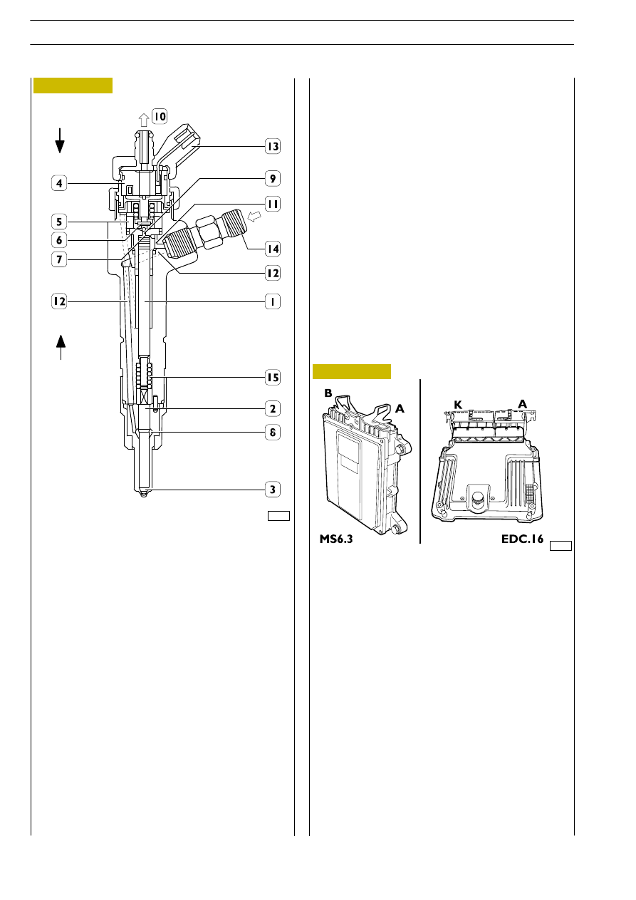
Figure 271
The coil (4) is energized and causes the shutter (6) to rise.
The fuel of the control volume (9) flows off towards the return
manifold (10) causing a drop in pressure in the control area
(7).
At the same time, line pressure through feed duct (12) applies
a force Fa > Fc in pressure chamber (8) lifting peg (2), with fuel
being consequently introduced into cylinders.
-
”end of injection”
The coil (4) is de-energized and makes the shutter (6) return
to its closed position. This recreates such a balance in the
forces as to make the pin (2) return to its closed position and
consequently end injection.
1 Pressure rod — 2 Pin — 3 Nozzle — 4 Coil — 5 Pilot valve —
6 Ball shutter — 7 Control area — 8. Pressure chamber —
9 Control volume — 10 Low-pressure fuel return —
11 Control pipe — 12 Supply pipe — 13 Electrical connection
— 14 High-pressure fuel inlet fitting — 15 Spring.
The electro-injector can be divided into two parts:
-
actuator/jet composed of pressure rod (1), pin (2) and
nozzle (3);
-
control solenoid valve composed of coil (4) and pilot
valve (5).
Operation
Electro-injector operation can be broken down into three
phases:
-
”rest position”
Coil (4) is de-energised, and shutter (6) is in closing position
and prevents fuel from being introduced into the cylinder, Fc
> Fa (Fc: caused by fuel pressure acting on control area (7) of
rod (1); Fa: caused by line pressure acting on pressure
chamber (8).
-
”start of injection”
50704
Figure 272
ELECTRIC/ELECTRONIC COMPONENTS
766161
Electronic control unit MS6.3 or
EDC 16
The control unit is a ”flash EPROM” and so it can be
reprogrammed from outside without changing the hardware.
It processes the signals from the sensors by applying software
algorithms and controls the actuators (especially the
electro-injectors and pressure regulator).
The injection control unit has the absolute pressure sensor
built in to further improve the control of the injection system.
The control unit is mounted on the left-hand side of the engine
bay and is connected to the vehicle’s wiring harness by two
43-pin connectors:
MS6.3:
—
43-pin connector A for the components on the engine
—
43-pin connector B for the components on the vehicle
EDC.16:
—
60-pin connector A for the components on the engine
—
94-pin connector K for the components on the vehicle
In addition to handling the operation of the system described
under the relevant heading, the electronic control unit is
interfaced with the other electronic systems on the vehicles
such as ABS — EBD cruise control, speed limiting device,
immobilizer (IVECO CODE), EGR and glow plugs.
90638
Fc
Fa
F1A ENGINE
D
AILY
414
Base - May 2004