Iveco Daily. Manual - part 108
72600
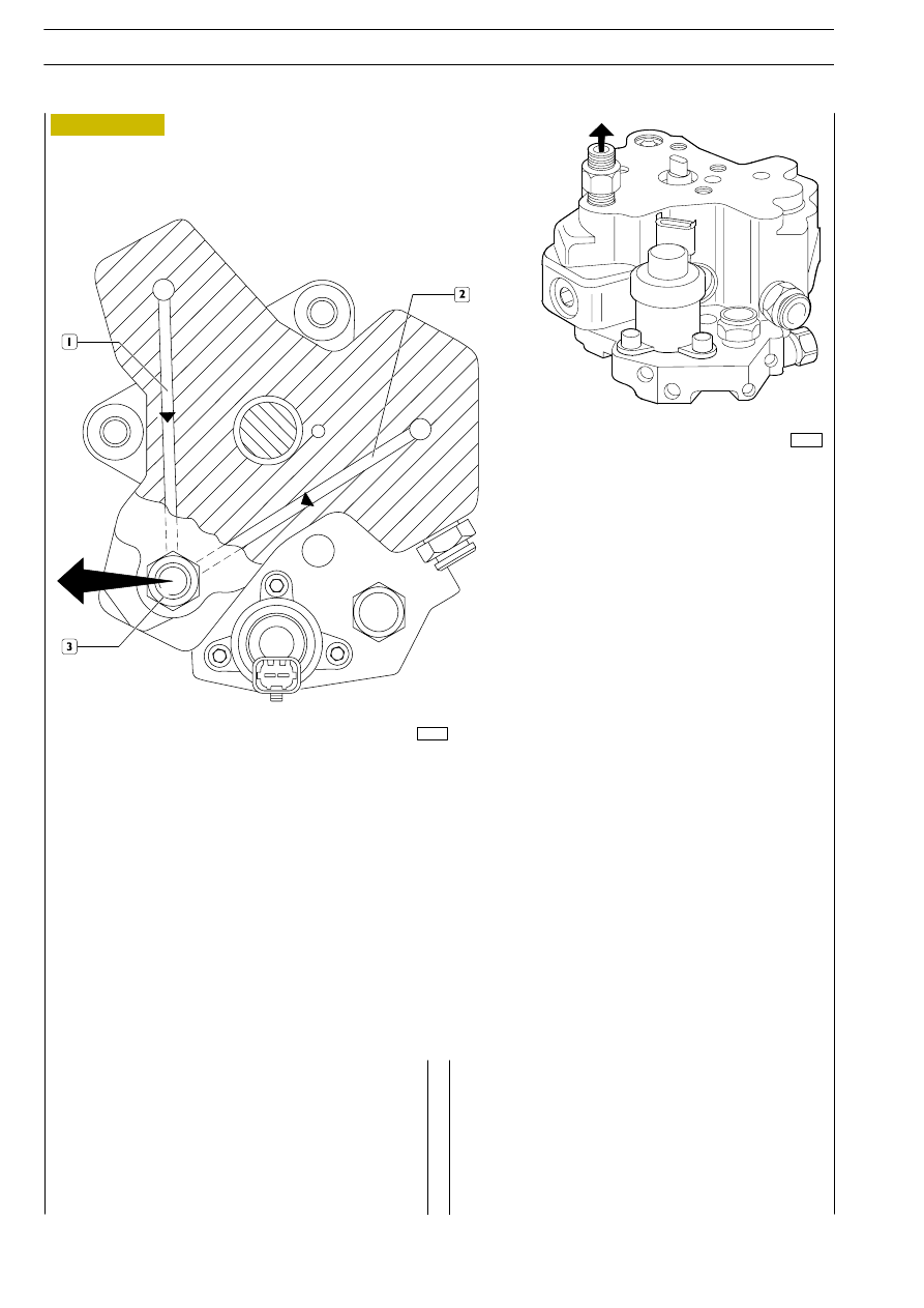
Figure 255
The figure shows the high-pressure fuel flow through the
outlet ducts of the pumping elements.
1, 2 Fuel outlet ducts — 3. Fuel outlet from the pump with coupling for high-pressure pipe for the common rail.
Sec. A — A (Figure 253)
72601
F1A ENGINE
D
AILY
410
Base - May 2004