Iveco Daily. Manual - part 104
75537
Intake exhaust
gas
Hot exhaust gasses
Engine coolant
Cold exhaust gasses
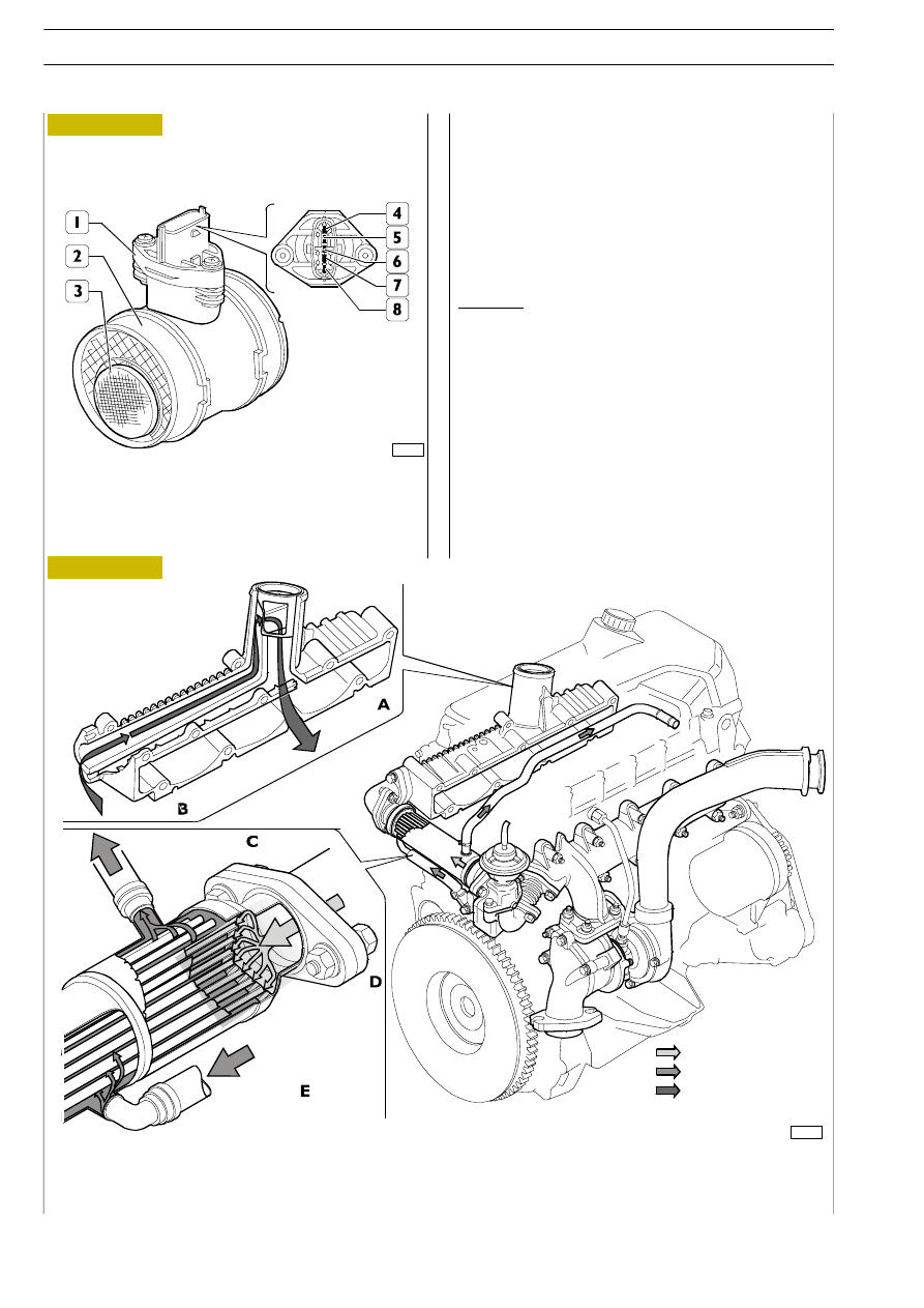
Air flow meter
1. Connector - 2. Flow meter body - 3. Air and
recirculated gas inlet mesh - 4. Suction air temperature
sensor - 5. Power - 6. Ground - 7. Reference voltage -
8. Output signal.
The heated film flow meter is arranged between the turbine
and the intercooler.
The suction air temperature sensor is built into the flow
meter; the flow meter is connected to the ECU pins
A5/A17/A18/A26/A28.
Operation
The hot film membrane temperature is kept constant
(approximately 120
°C higher than suction air temperature)
by a heating resistor.
The air mass crossing the duct tends to subtract heat from
the membrane. Consequently more current is required
through the resistor to keep the temperature constant.
Current uptake is proportional to the mass of air flowing into
the engine. It is measured by a Wheatstone bridge and the
resulting signal is sent to the ECU.
EXHAUST GAS COOLING
A. Intake exhaust gas — B. Cooled exhaust gas — C. Coolant to heater — D. Gas from E.G.R. valve —
E. Coolant arriving from cylinder head.
86036
Cooled exhaust
gas
Coolant to heater
Gas from E.G.R. valve
Coolant arriving
from cylinder
head
Figure 242
Figure 243
F1A ENGINE
D
AILY
394
Base - May 2004