Iveco Daily. Manual - part 102


  Index      Iveco     Iveco Daily - service repair manual 2004 year


Search            


Content   ..  100  101  102  103   ..


Iveco Daily. Manual - part 102


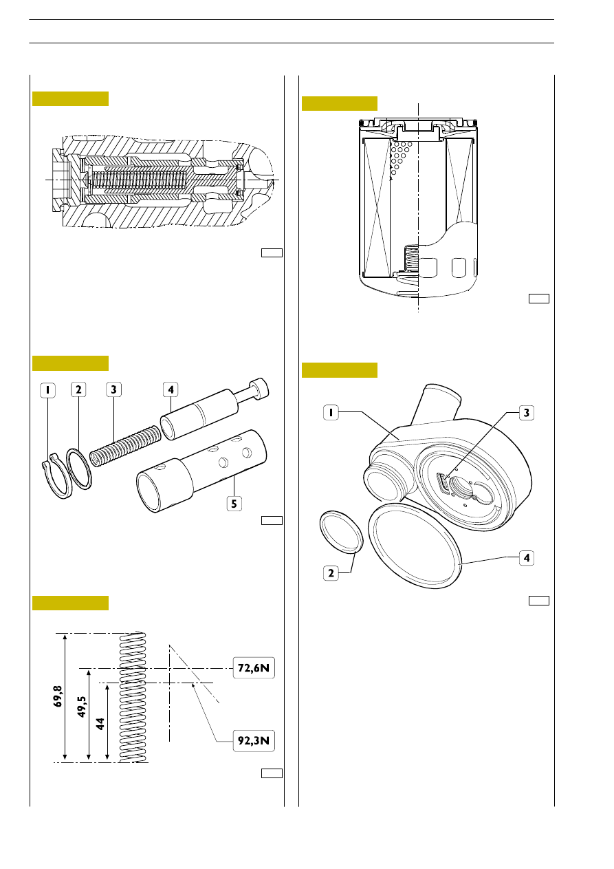
CROSS-SECTION OF OIL PRESSURE CONTROL

VALVE MOUNTED IN CRANKCASE

Valve removed from crankcase L = 51.75 mm.
Valve fitted in crankcase L = 50.75 mm.
Start of opening 4 bar L = 49.5
maximum opening 4.6 bar L = 44.

75520

Figure 224

Figure 225

Figure 226

543070

Oil filter

75521

75523

Figure 227

PARTS COMPRISING THE OIL PRESSURE

CONTROL VALVE

1. Split ring — 2. Washer — 3. Spring — 4. Valve —

5. Valve casing.

75522

MAIN DATA OF THE OIL PRESSURE CONTROL

VALVE SPRING

Oil filter with single filtration with built-in by-pass valve —
opening pressure 2.5

± 0.3 bar.

543110

Modine heat exchanger

75524

Figure 228

Thoroughly clean the heat exchanger (1).
Always change the seals (2 and 4).
Built-in safety valve (3).
Opening pressure

0.82 - 1.03 bar

543475

Oil pressure control valve

F1A ENGINE

D

AILY

386

Base - May 2004

Figure 229

540480

Oil vapour recirculation system

Description

The oil vapours formed in the sump while the engine is
running, passing through the overhead cover, are channelled
into the separator / condenser filter known as the blow-by.
The filter is structured in two sections:

- The first one with a labyrinth, where most of the vapours

are condensed and return to the sump through an
umbrella outlet valve.

- The second one includes a coalescence filter that

condenses the remaining vapours that return to the
sump through another umbrella valve.

The portion of vapour that has not condensed is sent, via a
MANN-HUMMEL valve, to the intake duct and burnt during
normal engine operation.

75525

OIL VAPOUR RECIRCULATION DIAGRAM

1. MANN-HUMMEL valve — 2. Umbrella valves — 3. Blow-by filter — A. Labyrinth — B. Intake oil

vapour recovery flow — C. Oil return flow into sump — D. Flow of oil vapours from the sump —

E. Flow of oil vapours from the overhead — F. Coalescence filter.

The blow-by filter cannot be taken apart and must
therefore be replaced entirely.

NOTE

F1A ENGINE

387

D

AILY

Base - May 2004

Figure 230

5432

COOLING

Description

The engine cooling system is the type with forced circulation
in a closed circuit. It comprises the following parts:

- An expansion tank whose plug has two valves

incorporated in it: an outlet and an inlet, which govern
the pressure of the system.

- A coolant level sensor at the base of the expansion tank.

- An engine cooling module to dissipate the heat taken

from the engine by the coolant with a heat exchanger
for the intercooler.

- A heat exchanger to cool the lubricating oil.

- A heat exchanger to cool the exhaust gases (engines

with EGR).

- A centrifugal water pump incorporated in the crankcase.

- An electric fan comprising an electromagnetic coupling

on whose shaft a hub turns idle that is fitted with an
axially mobile metal plate on which is mounted the
impeller.

- A 3-way thermostat governing the circulation of the

coolant.

Operation

The water pump driven by a poly-V belt by the crankshaft
sends coolant into the crankcase and with a greater head into
the cylinder head.
When the coolant temperature reaches and exceeds the
working temperature, it causes the thermostat to open and
the fluid is channelled from here to the radiator and cooled
by the fan.
The pressure in the system due to the change in temperature
is governed by the outlet (2) and inlet (1) valves incorporated
in the expansion tank filler plug (detail A).
The outlet valve (2) has a twofold function:

- to keep the system slightly pressurized so as to raise the

boiling point of the coolant;

- to discharge into the atmosphere the excess pressure

produced in case of high coolant temperatures.

The function of the inlet valve (1) is to permit transferring the
coolant from the expansion tank to the radiator when a
lower pressure is created in the system due to the reduction
in volume of the coolant as a result of its temperature
lowering.
Outlet valve opening 1

± 0.1 kg/cm

2

.

Inlet valve opening 0.005 — 0.02 kg/cm

2

.

75526

Hot

Very hot

Cold

F1A ENGINE

D

AILY

388

Base - May 2004

CROSS-SECTION OF THE ELECTROMAGNETIC JOINT

Characteristics
Transmissible torque at 20

°C with clutch run in

45 Nm

Voltage

12 Volts

Power input

26 W

The electric fan control relay is activated or deactivated
according to the temperatures of: the engine coolant, the fuel
supercharging air and the pressure of the air conditioner fluid
(if present).
Coolant temperature
(if the sensor is not defective)
It activates at > 96

°C and deactivates at < 84°C.

Turbocharging air temperature
It activates at > 75

°C and deactivates at < 65°C.

Fuel temperatures
(if the coolant temperature sensor is acknowledged to be
defective by the EDC control unit)
It activates at > 20

°C and deactivates at < 10°C.

With climate control system
With pressure in the system
it turns on

18.5

± 0.98 bar

it turns off

14.58

± 0.98 bar

75527

Figure 231

Figure 232

The water pump (3) cannot be overhauled. In case of coolant
leaking from the seal or damage, it must be replaced. The
water pump casing (1) is also used as a mounting for the
high-pressure pump. The seals (3 and 4) must always be
replaced.

75528

543212

Electromagnetic pulley

543210

Water pump

LONGITUDINAL CROSS-SECTION OF THE

WATER PUMP

1. Pump casing — 2. Pump drive shaft together with

bearing — 3. Seal — 4. Impeller.

Figure 233

75529

The by-pass thermostat (1) needs no adjustment.
If there is any doubt about its operation, replace it.
The thermostat casing is fitted with the thermometric
switch/transmitter and water temperature sensor.

A. — A1 Start of stroke at 78

°C ±2°C.

B.

Valve (1) stroke at 94

°C = 7 mm.

B1

Valve (2) stroke 94

°C, 6.4 mm

The stroke of 7 mm less than 60”.

543250

Thermostat

Figure 234

75530

F1A ENGINE

389

D

AILY

Base - May 2004


Content   ..  100  101  102  103   ..