Iveco Daily. Manual - part 64
86144
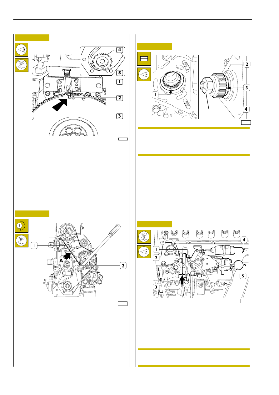
Figure 13
- remove engine flywheel (3) slit (
⇒) from tool 99395214
(1) pin (2);
- turn the crankshaft slowly in the direction of rotation by
two turns and check that hole (5) in gear (4) is facing
downwards and that the pin (2) of the tool (1) is inserted
in the slot (
→) through the flywheel (3) when the timing
belt is taut; the notches (1 and 2, Figure 10) must be
aligned.
- lock the tightener (2), tightening the fixing nut at a torque
of 37
÷ 45 Nm;
Use tool 99395849 to check timing belt tension (1) which
must be 88
÷ 112 Hz in point A.
61900
Injection pump assembling and timing
Connect injection pump on accessory equipments group
proceeding as follows:
- check for the exact timing of valve gear;
- Fit injection pump (2, Figure 16) on auxiliary component
unit (3, Figure 16). The spline (1) obtained inside pump
control shaft shall coincide with joint projection (3).
Position the injection pump on auxiliary component unit
so that marks performed at removal coincide.
- Screw pump fastening nuts (1, Figure 16) without
tightening them;
62081
- Remove the plug, situated on pump closing screw, and
screw tool 99395100 (5) with the rod in contact with
distributor piston crown;
- prevaricate dial gauge 99395603 (5) of
~ 3 mm;
- feed the thermal bulb (4) of K.S.B. device with a 12 V
voltage, throughout timing duration; in this way K.S.B.
device is cut-out.
52221
Figure 14
Figure 15
Figure 16
Should joint (2) be replaced, use tool 99365143 to
lock joint (2) rotation when moving nut (4) and tool
99342138 to remove the joint from injection pump
shaft.
NOTE
K.S.B. device is cut-out when advance changer lever
is no more engaged.
NOTE
ENGINES 8140.43C
DAILY
238
Base - May 2004