Iveco Daily. Manual - part 34
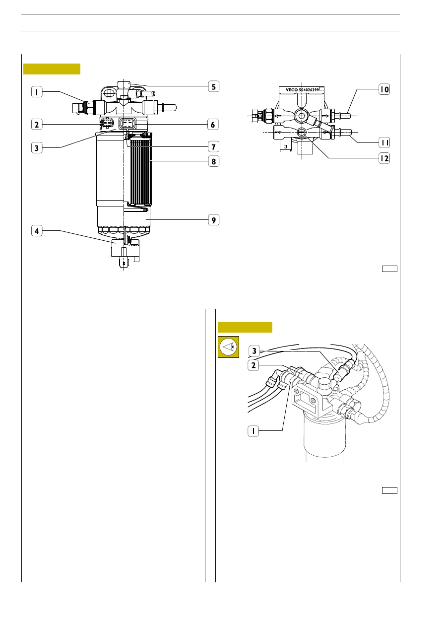
Figure 242
Fuel pipes
542011
Fuel filter
The fuel filter is composed of a cartridge (8) equipped with a
water separator (9).
The water accumulation capacity (A) of the filter is approx.
100 cm
3
.
The water indicator (4) is mounted on the bottom end.
Unscrewing the indicator (4) drains off any water.
Heater support (3) has an integrated temperature sensor.
On heater support (3) there are screwed up sensor (1) to
signal filter clogging and overpressure valve (5).
When the temperature of the diesel is less than 6
°C, an
electric heating element warms it up to at most 15
°C before
sending it to the pressure pump.
When diesel oil temperature is under 6
°C, a resistor heats the
oil up 15
°C maximum before delivering it to high pressure
pump.
Overpressure valve characteristic
opening pressure 1.8
bar
Clogging indicator characteristics
differential working pressure 0.8
bar
Tightening torques
1.
Tightening clogging signalling sensor
20
±2 Nm
4.
Water indicator
0.8
±1.2 Nm
5.
Tightening overpressure valve
25
±2 Nm
7.
Threaded insert *
30
±2 Nm
8.
Fuel filter tightening
18
±2 Nm
10. Connector
30
±2 Nm
11. Connector
30
±2 Nm
12. Bleed screw
12 Nm
*
Before assembly, apply thread-stop LOCTITE on the
thread.
88613
1. High-pressure pump supply pipe quick-coupling fitting —
2. Supply pipe quick-coupling fitting — 3. Fuel return pipe
quick-coupling fitting — 4. Fuel filter mounting.
If disconnecting the fuel pipes (1-2-3) from the mounting (4),
it is necessary, when refitting, to make sure their fittings are
perfectly clean. This is to avoid an imperfect seal and fuel
getting out.
75585
Figure 243
1. Clogging signalling sensor - 2. Temperature sensor connector - 3. Heater support - 4. Water in signalling sensor -
5. Overpressure valve - 6. Heater connector - 7. Bending insert - 8. Fuel filter - 9. Water separator - 10. Connector -
11. Connector - 12. Purging screw.
+ 0.2
- 0.3
+ 0.05
- 0.1
ENGINES 8140.43R/B/S/N
118
D
AILY
Base - May 2004