Iveco Daily. Manual - part 29
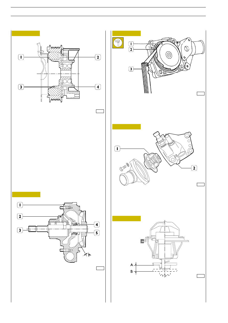
A. Stroke start 82
° ± 2 °C.
B.
Stroke at 97
° ≥ 7 mm
Stroke at 110
° ≤ 10.5 mm
The stroke of 7 mm within less than 60”
Water blow-by with thermostat and valve closed
≤ 2 l/h
543212
Electromagnetic pulley
50685
50686
41128
50687
50822
Figure 193
Figure 194
Figure 195
Figure 196
Figure 197
ELECTROMAGNETIC PULLEY SECTION
Use a thickness gauge (3) to check that the distance between
impeller (1) and sealing ring (2) is 0.56
÷ 1.08 mm.
Also check that there are no cracks in pump body. If there
are, replace the whole water pump.
By-pass type thermostat (1) is inserted into the support (2)
fixed to cylinder heads and it does not need any adjustment.
If there are any doubts about its serviceability, replace it.
The thermometric switch/transmitter and water tempera-
ture sensor are fitted on the thermostat body.
Specifications
*
Torque that can be entered at 1000 rpm
and at 20
°C
23 Nm
*
Torque that can be transmitted at 20_C
with the clutch run in
43 Nm
Voltage
12 Volt
Consumption
24 W
When cooling fluid temperature reaches the value of
94
°
± 2°C, thermometric switch allows electromagnet (1)
to be supplied and that, becoming magnetized, it attracts
movable plate (2) thus causing hub (4) to become integral
with electromagnetic joint (3).
543210
Water pump
WATER PUMP LONGITUDINAL SECTION
1. Pump body - 2. Bearing locking screw - 3. Pump driving
shaft complete with bearing - 4. Sealing ring - 5. Impeller
A = 0.56
÷ 1.08 mm; assembly clearance between impeller
and sealing gasket for water pump body.
543250
Thermostat
ENGINES 8140.43R/B/S/N
98
D
AILY
Base - May 2004