Iveco Daily Euro 4. Manual - part 174
 

  Index      Iveco     Iveco Daily Euro 4 - service repair manual 2006 year


Search            


Content   ..  172  173  174  175   ..


Iveco Daily Euro 4. Manual - part 174


88680

88681

88682

Figure 29

Figure 30

Figure 31

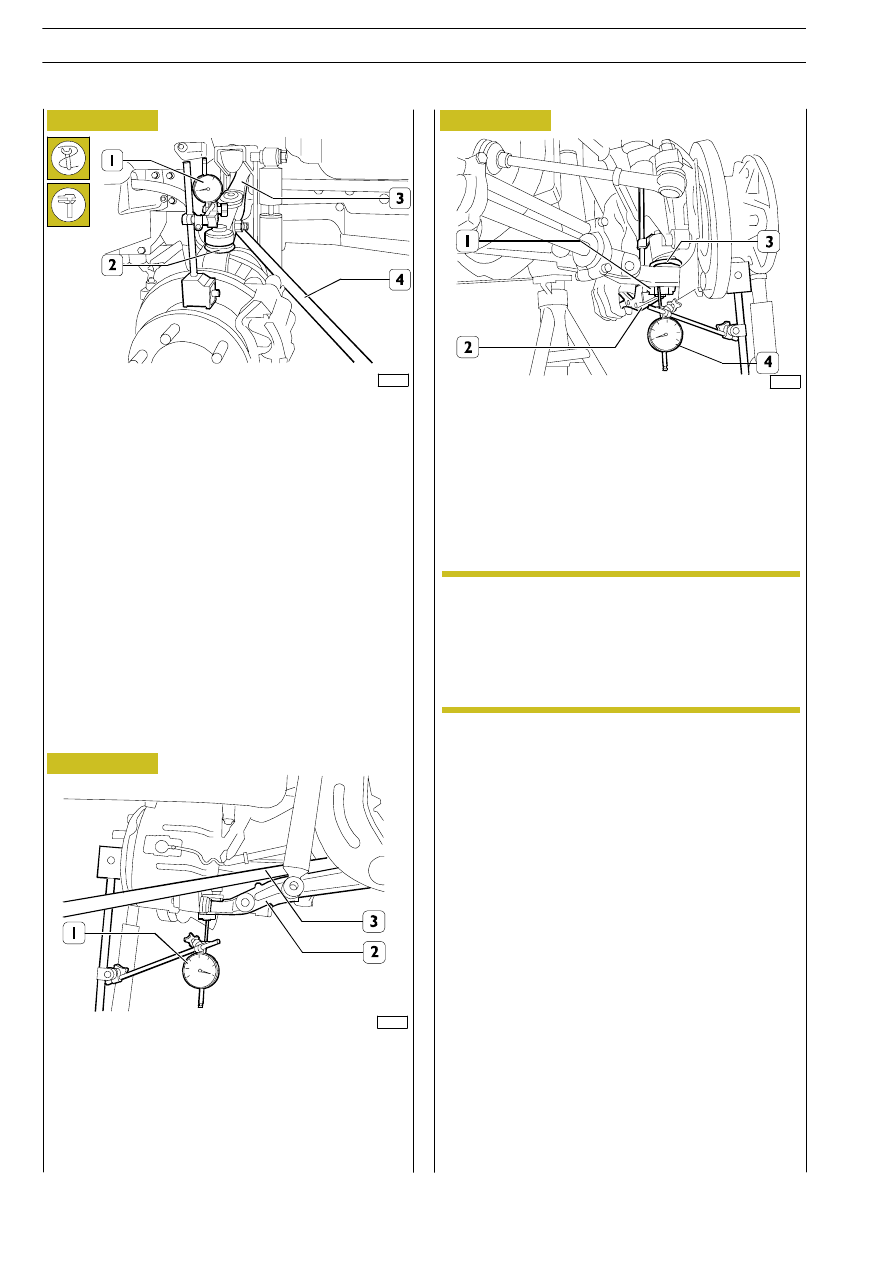
Pre-load comparator (1) by approximately 4 mm and reset
it by suitable lever (4), lift upper swinging arm (3) as much
as possible and detect the displacement of comparator (1)
hand corresponding to the clearance of articulated head (2).
If detected value is between 1.5 and 2.0 mm, the articulated
head (2) needs to be replaced, as described in relating
chapter.

Position comparator (1) tracer point with magnetic base
99395684 on the top of the articulated head of lower
swinging arm (2).
By suitable lever, lower swinging arm (2) and reset
comparator (1).

By suitable pliers (2) applied on articulated head (3) and on
lower swinging arm (1), apply strong pressure on head and
arm and write down comparator (4) hand displacement
corresponding to articulated head clearance.
If detected value is between 1.5 and 2.0 mm, the swinging arm
needs to be replaced, as described in relating chapter.
Remount dismounted parts in order to make checks.

Check the clearance of lower swinging arm
articulated head

See Figure 26: the nut for screw (3) to secure tie rod
(2) to lower swinging arm (1) and see Figure 25: the
nut (4) for the screw to secure lower swinging arm
(2) to cross member (3): they must be tightened at
prescribed torque with the vehicle lowered and
vehicle empty weight weighing down on suspension.

NOTE

32

FRONT MECHANICAL SUSPENSIONS

D

AILY

E

URO 4

Loosen the nut (2) and unscrew the swivel head (1) from the
bottom tie rod (3).
Screw the new swivel head (1) onto the tie rod (3)
positioning it at the values shown in the figure.
Tighten the nut (2) to the prescribed torque.

Figure 32

75360

44664

Figure 33

Figure 34

Figure 35

TIE RODS

Remove the stabilizer bar as described under the relevant
heading (operation 528030).

Take out the nut for the screw (2) securing the tie rod (3)
to the bottom suspension arm (1) and remove the screw (2)
from this.

Take out the nut securing the link pin (5) to the mounting (4).
Using the extractor 99347060, remove the swivel head (5)
from the mounting (4).

Take out the nut (3) for the screw (4) securing the tie rod
(1) to the top suspension arm (2) and remove the screw (4)
from this. Take out the nut securing the link pin (5) to the
mounting (7). Using the extractor 99347074 (6), remove the
swivel head (5) from the mounting (7). Remove the screw
stay (1) from the vehicle.

Loosen the nut (2) and unscrew the swivel head (1) from the
top tie rod (3).
Screw the new swivel head (1) onto the tie rod (3)
positioning it at the values shown in the figure.

Removal

If removing the mounting (7), so as not to change the
wheel geometry, not the number and thickness of
the spacers (if there are any) under the mounting to
mount them in the same way when refitting the
mounting (7).

500764

Replacing swivel heads

75359

Using the extractor 99347060 (1), detach the stub axle (2)
from the mounting (4) Figure 22.
Remove the screw stay (3) from the vehicle.

300.

4

±

0

,.6

364.5

± 0.7

3

2

1

19056

220

±

0.

5

378

± 0.8

44666

1

2

3

Figure 36

NOTE

FRONT MECHANICAL SUSPENSIONS

33

D

AILY

E

PRINT 603.43.351

500760

OVERHAULING THE SUSPENSION

Refit the top tie rod (5) to the top suspension arm (3) and
to the mounting (6).
Tighten the nut securing the link pin (1) to the required
torque.

Refitting

The nut (4) for the screw securing the tie rod (5) to
the lever (3) must be tightened when the load of the
empty vehicle weighs on the suspension.

44668

Figure 37

Refit the bottom tie rod (3) to the bottom suspension arm
(1) and to the mounting (4).
Tighten the nut securing the link pin (5) to the required
torque.

Figure 38

44664

At the end of the re-fitting check the wheels
geometry as described in the relevant paragraph.

Then tighten the nuts, which fasten the articulated
head to the relevant tie-rods, to the prescribed
torque.

The nut (2) for the screw securing the tie rod (3) to
the bottom lever must be tightened when the load
of the empty vehicle weighs on the suspension.

Re-fit the stabilizer bar.

Figure 39

Remove the nut which fastens the articulated head (2) of the
gearbox tie-rod to the steering knuckle; with the puller No.
99347074 (1) remove the articulated head (2).

44935

Removal

Remove the lower and upper tie-rods as described in the
relevant paragraph (operation 500761) and go on as follows:

Figure 40

Loosen the nut (2) and unscrew the threaded pin (1) until
the torsion bar (3) is fully ”unloaded”.
Take out the nuts (4) for the screws securing the mounting
(5) to the chassis frame.
Remove the mounting (5) from the torsion bar (3).

Remove the nuts securing the link pins (1) from the top (4)
and bottom (6) suspension arms to the stub axle (5).
Support in an appropriate way the steering knuckle (5)
together with brake caliper and wheel hub and with the tool
No. 99347074 (2) remove the steering knuckle (5) from the
levers (4 and 6).
Place the steering knuckle (5) on a support without straining
the brake fluid hose and the electrical wires.

44671

Figure 41

74997

NOTE

NOTE

NOTE

34

FRONT MECHANICAL SUSPENSIONS

D

AILY

E

URO 4

TORSION BARS

Remove the split pin (6), the nut (5) and the washer (4).
Disconnect the top suspension arm (2) from the cross
member (3) extracting the torsion bar (1).

19603

Fit the new knuckle pin (3) on upper and lower swinging arm
(1).
Loosen ring (2).

19602

Silentbloc is replaced using tool 99374241 (1); the limit stops
(2) are replaced with general tools.

19045

Replacing silentbloc and limit stops

44673

1

2

3

4

5

6

44672

Take out the nut (5), remove the screw (4) and recover the
two washers.

Disconnect the bottom suspension arm (3) from the cross
member (1) extracting the bushing (2).

Figure 42

Figure 43

Figure 44

Figure 45

Figure 46

Using tool 99357151 (1) loosen the ring nut and extract the
link pin (2) from the suspension arm.

Replacing link pins

1

2

FRONT MECHANICAL SUSPENSIONS

35

D

AILY

E


Content   ..  172  173  174  175   ..