Iveco Daily Euro 4. Manual - part 154
12
AXLE 5817
D
AILY
E
URO
4
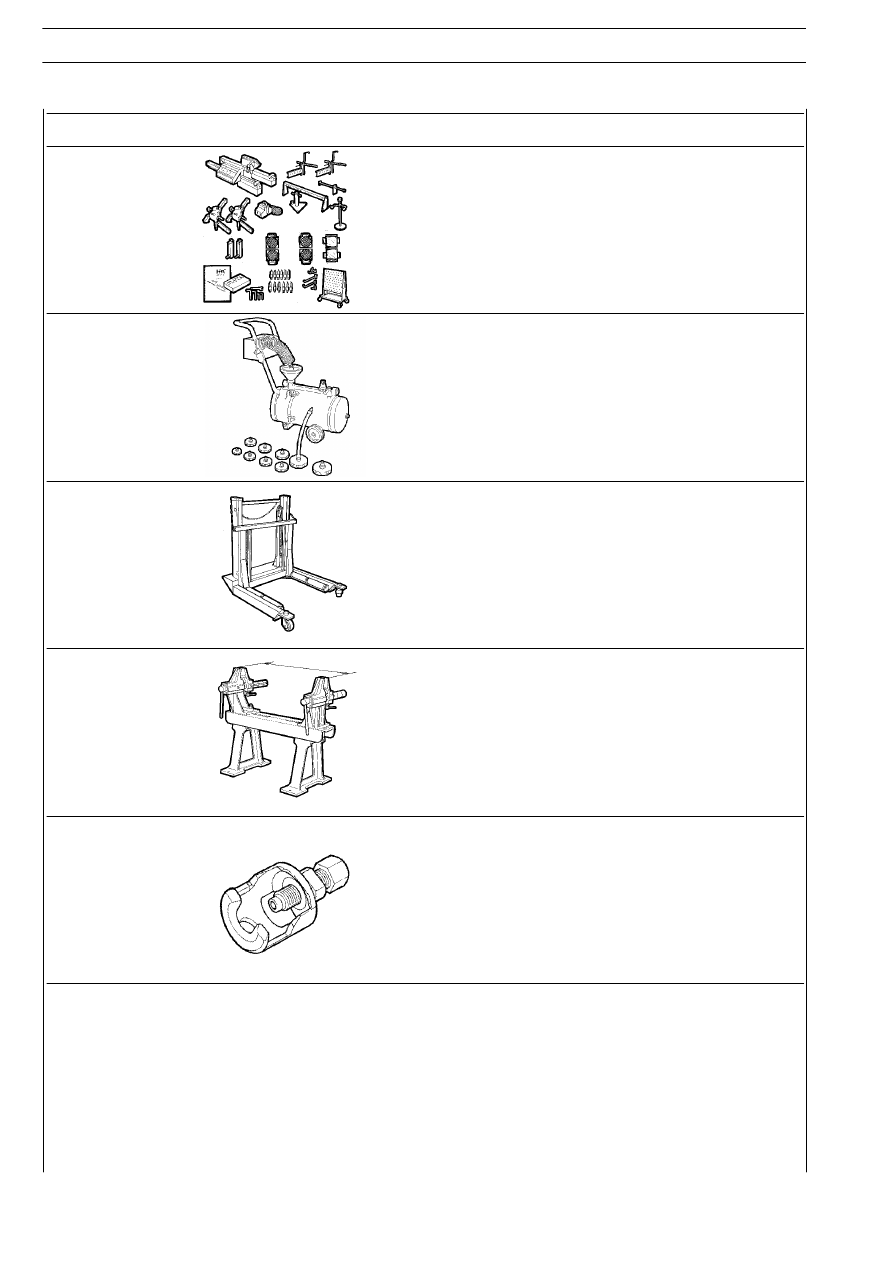
TOOL NO.
DESCRIPTION
99305354
Portable optical reading tool for checking wheel trim
99306010
Apparatus to purge air from brakes and clutch
99321024
Hydraulic trolley for removing/refitting wheels
99322215
Guide to wheel hub assembly
99347074
Puller for steering tie rod king-pins